The huge and powerful Create Tiled Clones dialog (Edit ▸ Clone ▸ Create Tiled Clones) is basically a tool for creating many clones at once. These created clones can be placed into many kinds of spatial and color patterns, ranging from absolutely regular to totally randomized. Moreover, you can also make these clones trace the image underneath them.
The first thing to do, before you can create a tiled clone pattern, is to select the object you will be cloning. I recommend using a group for that; even if you have a single object, group it ( ). This way, you will later be able to add more objects to the original group and the clones will reflect that. Place the original into the top-left corner of the area you want to fill with the pattern.
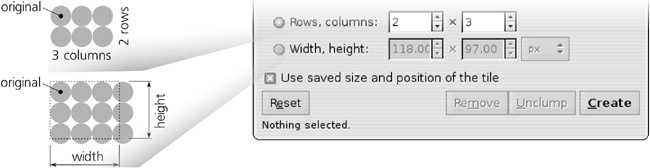
In the Create Tiled Clones dialog, start by specifying the size of the tiling (Figure 16-11). You can either give the number of rows and columns in the pattern, or if you have some specific area to fill, you can type or paste its width and height. Note that too-large patterns—with more than a few thousands of clones—can slow Inkscape down considerably.
To create a tile (after you set all other parameters as described below, or if you just trusted the defaults), click the Create button. The pattern appears on the canvas, but you still have the original object selected. The Remove button deletes any previously tiled clones of the selected object. Note that Create implies Remove—that is, once you click Create, any existing tiled clones (but not regular clones created by  ) are removed and replaced by a new pattern.
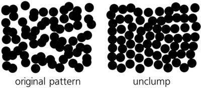
The Unclump button works exactly as the same-name button in the Align and Distribute dialog (7.5.1 Randomizing, Unclumping, and Removing Overlaps), except that it moves all the tiled clones of the selected object rather than all selected objects. Unclumping is especially useful for making randomized patterns more uniform without regularizing them. The Reset button changes all parameters of the dialog back to the defaults.
The Use saved size and position of the tile checkbox has no effect when you create a pattern for the first time. However, if you modify the object you’re tiling and create the pattern again, normally Inkscape will use the altered size of the object, which may result in the pattern changing its overall size and the alignment of the tiles. To make Inkscape use the same tile size as the last time you created a pattern from that object, even if the object’s size has changed, check this checkbox. For example, you can create a pattern from a rectangle, fine-tune all the parameters, then remove the pattern, scale up the original rectangle, and recreate the pattern with this checkbox checked. You will now have the exact same pattern as last time, but with its tiles larger and overlapping each other. (Of course, you can also simply edit the original without removing and regenerating the pattern.) Every object may thus remember its last “tiled size.”
Note
Note that all patterns include a clone that exactly (except when randomized) overlays the original object. This means that if you lose the selection of the original, simply clicking the original’s location will select the overlying clone and not the original. Use  -click (5.9 Selecting Objects from Underneath) or select any of the clones and press
  to jump to the original.
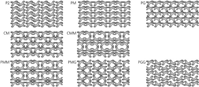
The first tab in the dialog is titled Symmetry. All it has is a list of symmetry groups from which you select one to use for your pattern. Each symmetry group is a specific way to transform the clones to form the pattern. It is not by a whim of Inkscape’s programmers that the number of these groups is exactly 17; mathematicians have proved that any possible regular pattern on a plane can be classified into one of these 17 types. For a complete description of each symmetry, see the Wikipedia article on “wallpaper group.” Here is an overview of the types:
P1
This is the simplest possible symmetry: The pattern tile is simply repeated in a rectangular grid without any rotations or flips.

P2, PM, PG, CM, PMM, PMG, PGG, and CMM
These symmetries use rotations by 180 degrees as well as vertical and horizontal flips in various combinations. However, all of these symmetries use the same rectangular grid placement as P1, with the width and height of the unit of grid being the same as width and height of the original object.
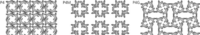
P4, P4M, and P4G
These symmetries involve rotations by 90 degrees, so they produce square-based patterns. The P4M symmetry results in partial overlapping of rectangular tiles; with it, use triangular tiles to avoid overlapping and fill the plane (Figure 16-15).
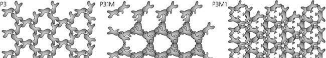
These symmetries involve rotations by 120 degrees and are thus roughly triangular in appearance. Again, P31M creates a more dense pattern with partially overlapping tiles, so you can use a “pie slice” shape to fill the plane with this symmetry without overlapping.
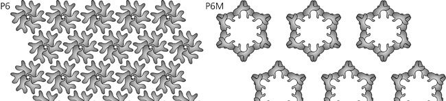
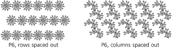
P6 and P6M
These symmetries rotate the tiles by 60 degrees, forming snowflake-like hexagonal patterns. Of them, P6M again overlaps the tiles and requires a “pie slice” shape to fill the plane without overlapping.
For “dense” patterns (P4M, P31M, P6M) that overlap the tiles, the following trick may be useful: Create the pattern and then scale the original down. This will make the pattern more sparse, and its characterisic logic will be easier to understand.
When working on a tessellation (a pattern that completely fills the plane without gaps or overlapping), it would be very difficult to create a tile of the proper shape in isolation, even if you understand well how your chosen symmetry works. Instead, just start with any random shape, create the pattern from it using the desired symmetry, and then node-edit the original path watching how the pattern’s clones repeat its changes. In this way, a surprisingly sophisticated tessellation can be produced very quickly (see 24.2 Treatment 2: Tessellation).
The next three tabs in the dialog allow you to specify the additional transforms to be applied to the pattern’s tiles—that is, transforms on top of those shifts, rotations, and flips implied by the chosen symmetry group.
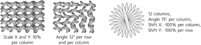
All of these additional transform components can be specified separately per row and per column, and each value can include a degree of randomness. You can specify, for example, an equivalent of “Make tiles in each next row 20 percent taller, rotate tiles in each next column by 5 degrees, and make the rotation angle vary randomly by 50 percent.” All shifts, scales, and randomization values are measured as percentages of the original object’s dimensions.
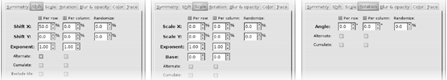
Here’s how it works for shifts:
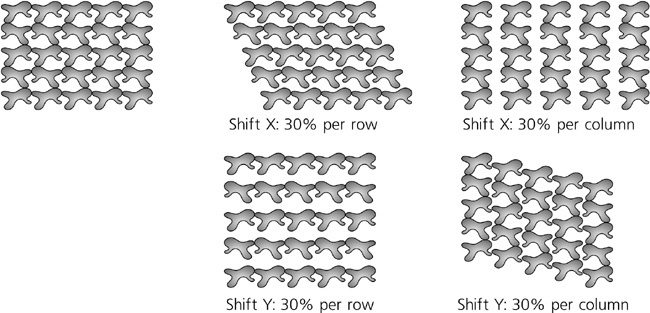
Negative shifts are possible, too. Naturally, to get all the clones to overlay the original, you need to specify Shift X: –100% per column and Shift Y: –100% per row. In combination with rotation per row, this makes it possible to easily create a flower or a clock face:
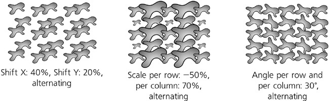
You can make the values Alternate (for example, scale clones in every second row). The Cumulate checkbox forces the values of shift or scale to accumulate; for example, normally a shift of 10 px per column means that each column is shifted by 10 px relative to the previous column. If you check Cumulate, the same value would mean every column being shifted 10 px further than was its predecessor—that is, the second column is 10 px from the first, the third is 20 px from the second, and so on.
For complex symmetries, a natural question is: What should be considered a “row” and a “column” when calculating transform values? Inkscape draws complex patterns by symmetric clusters (of 3, 4, 6, or 12 clones, depending on the symmetry), going from one cluster to the next horizontally within a row. In other words, clones that belong to one cluster are considered to be in the same row but in different columns. This means that the Per row shift values work by shifting rows of clusters or scaling clones in each cluster uniformly, whereas Per column values affect each clone independently, and as a result clusters lose their symmetry. If you want to space out symmetric clusters in both dimensions, just create a single cluster with your chosen symmetry, then group it, and tile the group with a simple P1 symmetry, possibly with alternating shifts.
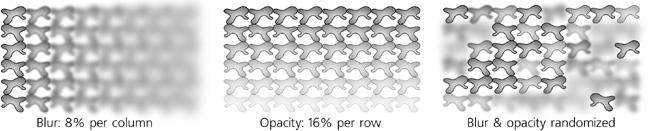
This tab of the dialog looks and acts very similar to the transform tabs; here, you can adjust the blur and the opacity (the Fade out value) of the clones in the pattern, per row or per column, with optional alternating or randomization. Remember that you can only make a clone more blurred or more transparent than its original, but not less.
As we’ve seen in 16.3 Styling Clones, if you want to paint a clone with its own color, you need to unset the corresponding property in the original. Once you’ve done that for the paint you’re going to change (fill, stroke, or both), the Create Tiled Clones dialog allows you to create a wide variety of color patterns.
The Color tab of the dialog looks very similar to all the tabs we already know. Here, you can vary any of the three components of the clone color in the HSL model—hue, saturation, and lightness (8.2.3 HSL)—per row or per column, as well as alternate or randomize the changes. You also need to specify the Initial color from which all these variations will start; just click the color swatch and use the color selector dialog. Remember that the original must have unset fill or stroke, otherwise this tab will have no effect!

For example, by starting with red and varying the hue by 5 percent per row and per column, you get a slanted rainbow, as shown in Figure 10 on the color insert.
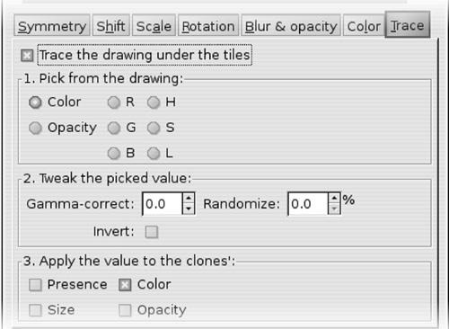
The last tab of the Create Tiled Clones dialog (Figure 16-25) is quite different from the rest. Here, you can make the pattern trace any kind of image on top of which it is built—that is, make it so that some of the aspects of each clone will depend on what is below it. The background image you’re tracing can be anything—for example, you can cover with the pattern an imported bitmap such as a photo, or you can draw anything with vector objects; it makes no difference to the tracer what it picks its values from.
The tab contains three main areas that correspond to the three main steps of the tracing algorithm. First, you pick some value at the location of each clone; second, you do some optional processing with that value; and third, you apply the result to some aspect of the clone. Enable the controls of the tab by checking the Trace the drawing under the tiles checkbox.
For the input value, you have the option of picking the Color, Opacity, or any single component of the color in RGB or HSL models. The value you pick for each clone is averaged over the entire rectangular area that will be covered by that clone’s bounding box. Of these options, all produce a single numeric value in the range from 0 to 1, except Color, which picks all three components of the color as a composite value.
The possible ways to process the value include:
gamma correction
Positive gamma shifts the picked value up, negative shifts it down.
randomization by a given percentage
The value will have a random component of the given size; 0% randomization means the value is exactly as picked, 100% randomization means it is totally random and does not depend on the picked value at all.
inversion
Turns high values into low and vice versa.
If a color is picked, this processing is applied to each of its components independently, as shown in Figure 11 on the color insert.
Finally, the resulting value can be applied to the clone’s probability of presence (0 translates into absence of the clone at this location, 1 into presence, and intermediate values make it appear with this given probability); color (this can directly reuse the background color if it was picked; otherwise, it translates single values to shades of gray), size (from disappearance at 0 to its full size at 1), and opacity (smaller values make the clone more transparent). Any number of these options can be enabled at the same time; for example, you can pick lightness, invert it, and apply it to both the opacity and size of the clones (see Figure 12 on the color insert).