Service Creation and Service Function Chaining
Abstract
Here we nominate what goes into defining a service today and the need for change that is inspiring NFV. We discuss the components that are needed to define the salient components of a service, as well as discuss the pitfalls of some definitions. We discuss the concepts of service paths, and how services can be defined as composites of other subservices, as well as how these components can be chained together.
Keywords
Service creation; SFC; IT applications; ETSI; IETF; network service; service function; service chain; virtualization
Introduction
Whether we’re talking about corporate/enterprise/IT applications and networks that support them (in order to provide competitive advantage within a vertical business grouping), or the services created by carriers in support of, or to entice/secure the business of, enterprise or broadband subscribers, network operators (enterprise or service provider) differentiate through service creation.
In this chapter we will take a preliminary look at the historical problems in service creation that drive the ideas behind service function chaining (SFC) and the potential of the SFC solution. In latter chapters, these will be refined in our discussion of efforts to standardize and optimize the solution space of SFC.
Definitions
Anyone involved with one of the numerous Standards Development Organizations grappling with Network Function Virtualization (NFV) will notice that there is a lot of debate over simple terminology. This often leads to arguments, confusion and a general lack of understanding of what is trying to be accomplished.
For the sake of making this book easier to follow, we will choose a set of terminology and (hopefully) remain consistent throughout the text. Because we will go into greater detail on both the ETSI and IETF work around SFC, this will not yet be exhaustive, nor is it necessarily authoritative. We are sure our editors will hound us for future updates to this text in order to keep up with the evolution in this space.
Network Service—A network service is any computational service that has a network component. Some of these functions can discriminate or otherwise manipulate individual network flows. Or as the IETF SFC Architecture document defines it: “An offering provided by an operator that is delivered using one or more service functions.”
Service Function—Again, the IETF document does a good job here in its definition: “A function that is responsible for specific treatment of received packets.” Of course, a network element providing a service function, be it virtual or the traditional, highly integrated device (described below) may provide more than one service function—in which case we would call it a “composite” service function.
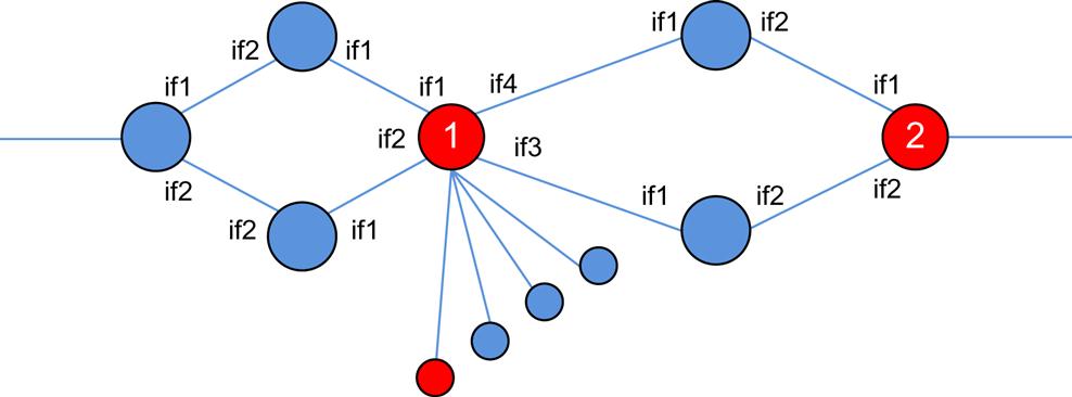
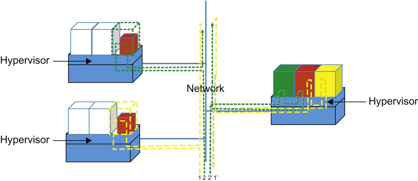
In the illustration in Fig. 2.1, the service may be an access application that requires two distinct functions for the service. If it helps to give a more concrete example, think of these functions as a firewall identified as the node numbered “1” and a Network Address Translation function as the node numbered “2.” These virtualized network functions are connected together and may forward traffic to and from each other as if they were real devices with physical cabling connecting each.
Service Chain—A Service Chain is the ordered set of functions that embody a “service.” This is generally the case excluding the derivative cases where a “service” can be delivered via a single function or a single composite function (eg: our “base” case in the preceding chapter). Services that are chained also imply an ordering or direction of traffic flow across service functions. That is, services can be chained in a unidirectional or serial fashion, where traffic enters on the left-hand side, traverses the services left-to-right and exits at the right-most service point.
However, Services can be chained in arbitrary ways too. Given the example from Fig. 2.1, one can imagine traffic entering on the left side of service function 1, being processed, and leaving via one of the links to its right and being passed to service function 2. However, we strongly recommend that the service definition include not only the functional definitions but also order of their traversal in the definition of the chain. So, using Fig. 2.1 as an example, we could define the traffic flow as {<if1> → function1 → <if2> function2 → egress <if3>} meaning that traffic enters function 1 via interface 1, is processed, exits via interface 2, goes to function 2 and is processed, and finally exits via interface 3. Also please keep in mind that as we previously mentioned, this does not have to be a linear progression, as some services can and do “branch” (eg, depending on the result of the function operation), so more complex definitions are possible.
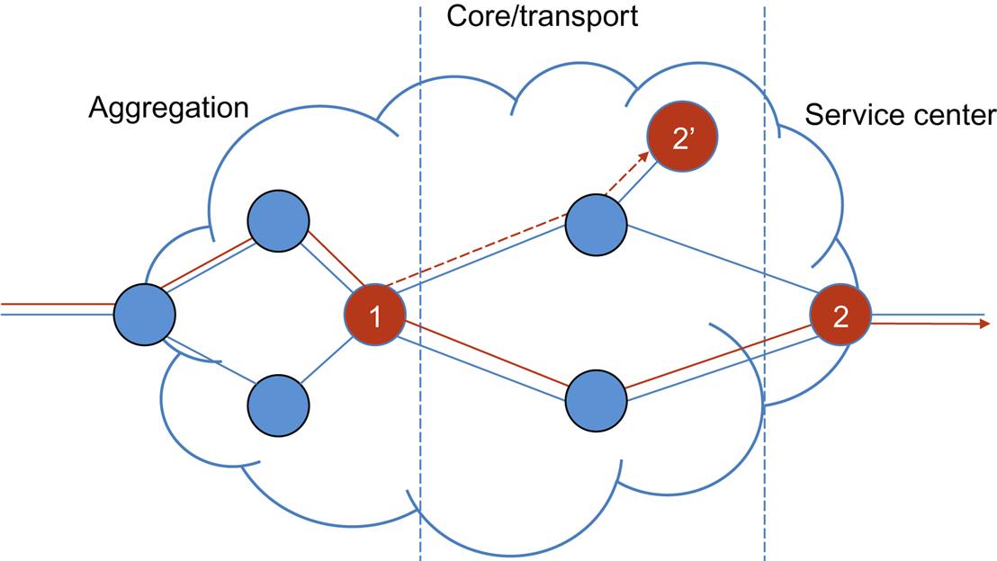
Fig. 2.2 illustrates a hypothetical branching service chain. Initial classification may direct the flow to service function 1. Normal processing would result in the forwarding of the network flow to service function 2 via the lower interface. However, when function 1 is executed, the flow might exceed an operational threshold or fail some inspection step that results in redirection to an anomaly treatment service function using the upper interface towards 2′. (For example, function 1 could be a DPI service that detects an embedded attack and forwards the traffic to a mitigation/logging function—which may be located more centrally in the network.)
The expression of this chain might look like {<if1> →lambda (function1) → (<if2> function2 → egress <if3>, <if3> function 2′ → egress <null>)}.1
Service Path—The Service Path is the logical path within the forwarding context between the service functions. The actual path is determined by the classification of a flow at any given point in time. The service path identifies the service and thus the chain of service function points that the flow traverses for inspection, processing or treatment if any exists other than default forwarding. Note that there is nothing in the definition of the service path that says how the flow should get from ingress to the first entity in the path, the first entity to the second entity, or the second entity and egress. The purpose in this ambiguity is to allow the operator to deploy a number of networking strategies: VLAN segmentation, overlay routing, etc. and if they choose, to simply allow for a default “shortest path” forwarding.
In our example (Fig. 2.1), the service path identifies specific network entities that the flow should visit in order to experience the defined service {address_function1, address_function2}. Conversely, the set of resulting nodes can vary and depend on the actual run time state of the system as is shown in Fig. 2.2.
Service Instance—A Service Instance is a further logical construct that combines with the service path to allow for service elasticity. The path should get the flow forwarded to a particular location in the network that in the abstract we call a “node.” A node may in turn share through a number of potential mechanisms, an address. This in fact can be implemented as a pool of instances of a function if one considered “cloud” instantiations of the functions as separate servers, Virtual Machines (VMs) or containers that are managed to scale with demand.
In our example (Fig. 2.1), the first identified function (function1) may be managing a larger pool of devices that execute its associated function. The highlighted device is an instance of the service, and as such a number of them may actually exist at any given time. For example, in a multi-tenant cloud environment, different instances of a firewall function might exist and be instantiated to process traffic per tenant. In this way, the service description, definition and chain can be viewed much in the way as service templates. The selection of the instance and its management can be done locally by the macro entity identified in the path or globally/centrally (eg, by a controller).
Service Templates—A Service Template is simply what one expects—it is pattern of one or all of Service Functions, chained together to for a service archetype. This pattern can be instantiated at will, within a certain context (ie, tenant, customer, etc.). This concept is similar to, and often implemented as, workflow automation in operational support systems.
The critical aspects in the definition of SFC include the abstraction between “chains,” “paths” and “instances.”
The power of these abstractions is in the elimination of unnecessary friction in service management. For example, a single chain can manifest as many service paths such that a large operator (eg, multinational) may select geographically appropriate instances for the path thus eliminating the need to manage geographically specific chains and allowing the flexibility to use instances from a wider range of function elements. Similarly, the service instance allows a single addressable service function to become logical—hiding an expanding and contracting pool of instances that are not explicitly exposed in the service path. This in turn eliminates the requirement to manage a service path per instance.
What we have not yet defined, but is just as critical to SFC, are the roles played by management and policy. These include considerations such as business, security, and network elements in the creation of “paths” from “chains.” This part of the picture will fill out more when we get to the details of work in various standards bodies related to SFC.
The Service Creation Problem
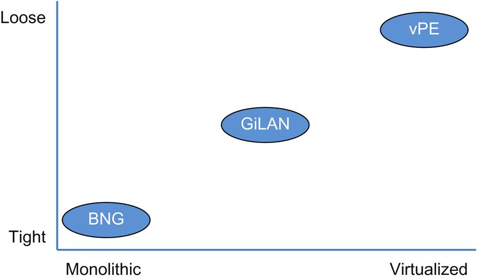
Until the advent of formalized SFC, most service offerings required highly integrated devices that were typically packaged as a single physical network element. By leveraging some clever tricks in DNS and IP addressing, some services started to appear as a more loosely coupled group of network elements (providing some lateral scalability) while remaining still highly pipelined or chained from a networking perspective. However by combining the virtualization of NFV with the locational independence of SFC, we can create, destroy and modify very loosely coupled services at very rapid rates. Moreover, we can augment those services on the fly in some cases, with a few keystrokes or even in an automated fashion.
Examples of this evolution are depicted in Fig. 2.3.
A Quick History
Historically, when a service was deployed, each of the physical service elements comprising the service had to be manually coupled together, most often by deploying new/more devices and physically connecting them together. While these configurations were closed, proprietary, and limited to a small set of specific functions, a network operator was free to arbitrarily chain them together as needed.
An evolution of this approach occurred when some products could support multiple service functions on a single physical device. These services were sometimes “sliced” in that multiple copies of the same service could execute within rudimentary environments that were the precursor to the modern hypervisor. Inside of these offerings was (arguably) the start of NFV as well as SFC.
Since functions were colocated on a single device, this at first limited most physical changes to things such as running short cables between line cards on the same box, and ultimately eliminated physical change by moving the cabling to internal connections that could be programmed in software.
While network services could be manipulated arbitrarily on these devices, they were still limited to the confines of that device and functions offered. So network services implemented within these closed, proprietary systems that needed to be chained with those on other devices to create services, ultimately still required physical intervention.
While generally rare and not obvious to most at the time, the Virtual Network Function did exist. For example, a few cases such as DNS, DHCP, and Radius could execute on general compute, but were generally not viewed as a virtualized service function, nor were those services viewed as “chained” together with others.
Most recently, modern NFV generalized such specialization into virtualized service functions that execute within a virtualized environment on Commercial Off The Shelf (COTS) compute. These environments are connected via networks that allow for easy and seamless multi-tenancy, in many cases without the network functions being aware that they are executing in such environments.
Since these virtualized elements all run within the context of a virtual environment, including the networks that attach them, operators are now free to move or change them without the burden of physically doing anything. What the virtualized storage, compute and network environment now represents is a general substrate in which to position and manipulate these resources. Of course, these virtualized elements are at some point, connected to at least one physical network element, and in some cases are connected multiple times in heterogeneous configurations but the point is that an entire virtualized world can be created to create and maintain the services that requires nearly no physical cabling or manual intervention to standup, modify, or destroy.
What was just described is referred to as Network Service Chaining (NSC) or SFC. SFC and NSC expand the reach of NFV, by allowing autonomy in the physical placement of the elements, enabling the concept of a Service Overlay.
In doing so, NSC/SFC trades off some performance that was afforded in more tightly coupled service architectures, as compensation for the freedom of general function positioning.
We can take a closer look at the evolution from tightly integrated solutions and “loosely coupled appliance” techniques and explore their limitations to appreciate what a virtualized service overlay might offer.
Tightly integrated service solutions
In a tightly integrated offering as is depicted in the bottom left of Fig. 2.3, the problems in service creation are many. We discussed some of these earlier in this chapter, but they are generally related to increased friction and cost around services deployment.
There are several business-related problems that impact the profitability of service providers that use tightly integrated service solutions to create revenue opportunities:
• An operator could be locked into certain services architecture by going with a particular vendor. If one vendor prefers one type of provisioning mechanism and supports some set of functions, and a new one comes along that supports one that is needed for a new service, this introduces undue friction in deploying that service.
• A vendor might employ a pricing strategy that might incentivize customers to purchase certain well-packaged solutions that work well within the confines of those supported, prepackaged service functions, but not with others. This also introduces potential friction to services deployment.
At the macroeconomic level, tightly integrated solutions can impact customer–vendor relationships. Purchasing leverage is constrained where a lack of competition exists towards the bottom left of Fig. 2.3, or may be enabled by competition towards the top right. In general, network service solutions have come from a handful of vendors, and they have dominated the service function market with their often proprietary and invariably antiquated interfaces to their equipment that dictate behaviors in the OSS.2 However, as we move towards the world depicted in the upper right of the figure, the disruption of challengers emerges.
There is a laundry list of operational concerns with highly integrated service architectures, including:
• The chosen vendor may not have expertise in all the related functions resulting in weaker implementations.
• The vendor implementation may not be at all modular or interoperate with other vendors’ offerings.
• The vendor software maintenance strategies may not allow easy patching and fixing (Service Software Upgrade).
• Time to market constraints due to the fact that service functions must exist on proprietary hardware. Solutions must be implemented by the vendor and thus cannot be deployed until such time as said vendor implements the function.
The overall combination of a poor vendor architecture/development cycle and an operator upgrade cycle that is spread out to minimize risk and churn can at best create undue resistance to service deployment velocity, but at worst, create a bottleneck to innovation and evolution of services.
Implementations of tightly integrated service platforms often have to balance the management of state with network forwarding capacity, resulting in somewhat rigid designs that balance service blades and network blades connected to a common fabric. The result of such a trade-off is that service deployment flexibility and agility suffers.
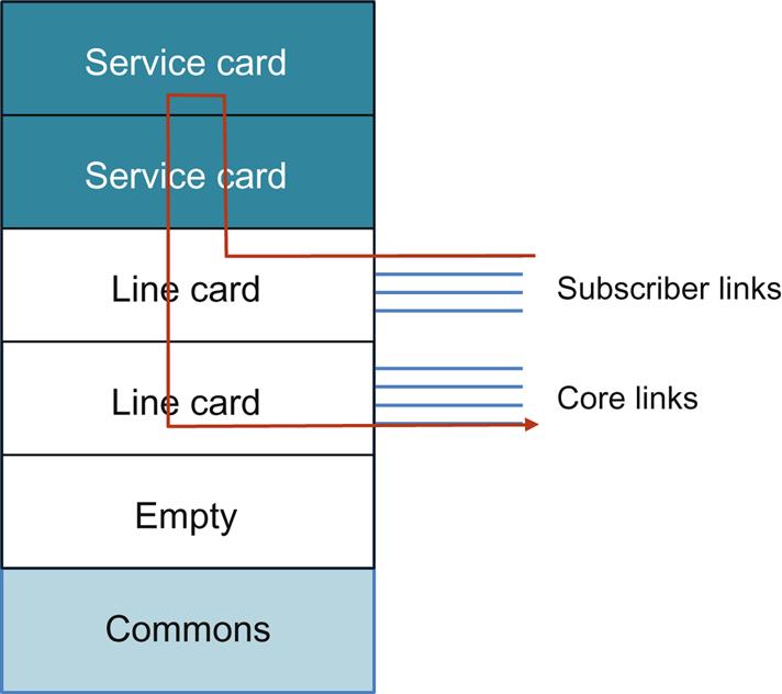
For the broadband network gateway (BNG) example (Fig. 2.4) typical designs are implemented as a modular chassis containing blades that implement different service functions. One generation of service blades may be designed and used to scale a certain number of control sessions (Radius/PCEF), subscriber state management, address assignment services (DHCP), DPI (APPID), and NAT (this is a nonexhaustive list).
As generations progress, subsequent generations are often designed with more scalable versions of these existing services, but sometimes less scale is possible as a sacrifice to supporting some newly introduced service function.
The internal connectivity between a service card and the forwarding line card may be (worst case) statically allocated through a command line interface (CLI) or dynamically allocated through a management demon in the bundled operating system.
Operators calculate and size these devices to support services they sell (such as broadband subscriber access) that are mapped onto the aforementioned functions that are chained together on the BNG.
If the operator miscalculates the nature of service uptake at a particular point of presence or if the vendor provides poor matches because of internal environmental limits that exist on the service cards such as chassis power or mismatches in the line/service card capacities, these capacity limits can result in unrealized opportunity or valuable assets stranded. Worse, service providers might continue to miss opportunities to sell new services when delays are encountered racking and stacking a new device.
The operator is not spared the challenges of elasticity or high availability by this high level of integration, although some of these architectural hurdles can be internalized within the vendor architecture through high availability of these systems such as dual control processors for the platform, active–active/active–standby state management across cards within a system or external system pairing using a heartbeat mechanism and some protocol that asserts a common next-hop IP address. These additions sometimes require additional hardware such as monitors within the chassis and redundant physical elements.
Note that one of the “features” (satirically speaking) of the highly integrated elements is the inability to pool resources between multiple elements.
With these tightly coupled elements, it should be obvious that new services (eg, requiring a new function that can be used in a different combination with existing service elements) are predominantly implemented by the device vendor. That is, the operator cannot build this himself/herself on the device, nor can they purchase the function from another vendor and run that on this hardware.
As the demand for features (functions required to implement an additional or enhanced service) across a vendor’s customer base for a device grows, production of any one feature may slow, resulting in another related problem with tightly integrated systems called feature velocity friction.
This results in a similar service deployment velocity at customers using those devices as they wait for new software and hardware to be delivered.
A network operator can choose to purchase an alternative device from another vendor, but at the added expense of integrating a new system into their network and operations. Depending on how “sticky” a vendor can make their device, this can lead to what is often called a vendor lock-in.
Loosely coupled—toward NFV/SFC
Like the BNG, the Gi-LAN was originally a very tightly coupled service (Fig. 2.5). Until approximately 2010, the Gi-LAN designs were like those in the (A) section of the drawing. The chain per customer from the Packet Gateway (PGW) was varied in the functions themselves, unshared and physically rigid.
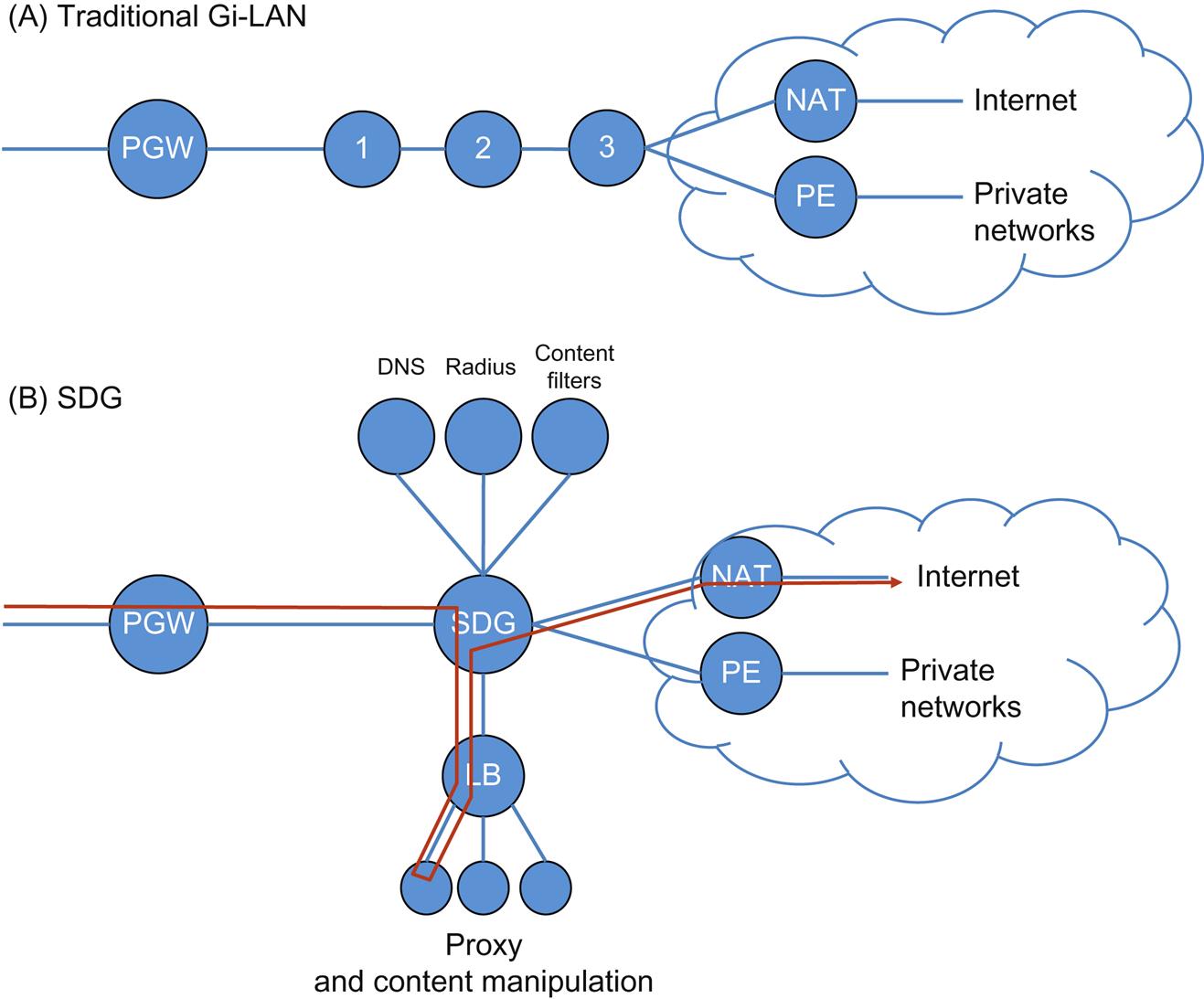
Around 2010, the Service Delivery Gateway (SDG)4 allowed for a loose coupling for more specialization in the functions, albeit still with dedicated appliances. Over time, further evolution of the mobile architecture (in general) has occurred to take advantage of SFC.
Note that in the illustration above, the SDG is working as a classifier and implements policy. All of the subsequent functions are constrained to a logical one-hop radius, creating a physical pipeline in a constrained topology with basic service steering by the aforementioned policy.
In solving some of the problems of tightly integrated solutions, however, a few new problems in service creation are introduced.
The first of these new problems is configuration complexity.
This affects operational costs. If each function supports a different methodology for configuring the service and managing the device, integration becomes even more difficult. Naturally, there should be less of a concern if the products come from the same vendor, but this is not always the case (eg, acquired products can take a while to normalize themselves to the acquiring vendor’s CLI semantic and syntax or OSS methodologies and hooks). This can leave the operator with the same potential vendor lock-in and services deployment velocity dilemma described in the tightly integrated solution.
There are lesser complications arising from the configuration complexity around the capability of the functional components to process configuration changes, which can be limited but not eliminated both by chosen protocol and vendor-implemented methodology. Historically, these arcana led to the rise of intermediary mitigation systems such as solutions from BNG, CA, Op-Net, and Tail-F. These systems masked the proprietary command lines and configuration quirks of various vendor devices through the insertion of extensible middleware and superimposed a transaction-processing framework for commits that spanned multiple devices. These innovations are examples of the start of the loosely coupled service architecture.
The second problem introduced is the “passing a clue problem,” which we refer to later as metadata.
Logically, when we broke apart the highly integrated system, we also removed any proprietary/internal methodology used to route the packets (flows) between service functions and/or provide accumulated information between the services (eg, subscriber/session ID). In the tightly integrated solution, this may have been accomplished using nonstandard extensions to fabric/buffer headers, using process shared memory pointers or an inter-process pub/sub data distribution service. Once externalized, these functions will reside in different machines and need to use standard transfer protocols for such information exchange as they no longer share common process space/environment.
In some loosely coupled solution spaces, this has been addressed through external arbitration (eg, policy servers and radius/diameter—as in Fig. 2.5). These schemes have their own architectural considerations for dealing with signal density and data distribution issues such as scale and the ubiquity of client software. This often introduces issues of openness and complexity.
A third problem arises by distributing the burden of classifying the traffic—mapping a flow to a subscriber and/or service.
• Classification engines within a forwarding device create additional overhead both in table memory and operations/cycles per packet. Without the deployment of costly, always-on classification tooling such as Deep Packet Inspection, all traffic traverses the pipeline as is shown in Fig. 2.5A.
• In multiple function, multiple vendor environments, the ability to classify traffic (more specifically, the ability to process a certain number of tuples at line rate), and the speed and method of updating classification rules can vary.
• On some platforms, particularly COTS/x86 compute, this is particularly onerous. While numerous tricks such as flow caching can be deployed to accelerate classification, there is a session startup cost and associated cache management concerns. Both the performance and scale of caching and flows are the focus of several recent research works.5
• Finally, in an increasingly encrypted world that is in part motivated by a backlash to the NSA headlines of today, classification in the service pipeline will become increasingly difficult if not nearly impossible. This is true particularly for flows that are classified by looking into the application-specific headers.
Both loosely coupled and highly integrated service solutions are also burdened by a lack of topological independence.
That is, they depend on the physical location of a physical device, and how it is connected to other physical devices. This static nature manifests itself as an impediment to deployment. That is, the envisioned service must be carefully planned in terms of not only capacity and performance of the service, but also as a physical device provisioning exercise as well as a geographical planning exercise.
These additional planning steps drive significant deployment cost that will be assumed in target markets by placing the device(s) with some preliminary scale. For an example, see the balancing problem above for highly integrated devices and imagine the additional calculus required in determining the initial scale and service component ratios within the device for a new market deployment.
The loosely coupled solution is arguably more flexible when coupled with the abstraction of a programmable overlay—commonly VLAN stitching or Layer 3 overlay. However service chain changes (which will require synchronization) or new service additions require topology changes and may present logical scale problems (eg, reaching the VLAN limit for per-customer services when using VLAN stitching6) (Fig. 2.6).

As an example of the previously mentioned “calculus”, imagine an operator decides to deploy a security service that requires vendor X’s firewall and vendor Y’s Intrusion Detection System (IDS). The operator’s research points to 10 markets where the service should be introduced, each with a varying percentage of existing/new subscribers that may want to purchase the service offering and with different historical service up-take patterns. Appliance X comes in two and four slot variants, each capable of 10 Gbps/slot, while appliance Y has two nonmodular versions, one capable of 20 Gbps and one capable of 40 Gbps. Also as is typical, the per-port cost of the four slot modular chassis will be cheaper than that of two of the two-slot model.
• Does the operator go solely with deployments with the four-slot model of X only to more effectively manage inventory and the upfront cost, even though 2 of the 10 markets are projected to take a very long time to grow to that amount of throughput? Consider the time it takes to actually fill those devices at full utilization and the cost depreciation model coupled with year-over-year price reductions of the device.
• Does the operator go solely with the larger appliance Y for similar reasons or multiple smaller instances to grow incrementally but at a higher base cost? What if that incremental growth is impossible to equally balance from appliance X—potentially requiring another appliance to effect load balancing?
• What if either model’s growth slows or increases mid-way through the service history?
If the service device in question does not directly terminate the subscriber circuit, it had to be deployed inline with the normal SPF routing/forwarding progression from the terminating device to ensure proper flow traversal as well as proper application of the service.
Arguably, overlay/tunnel technology coupled with the use of anycast addressing or SDN control can be leveraged to loosen these planning and placement constraints and limitations. It is fair to point out that these could be at the potential cost of bandwidth efficiency (the flow “trombones” back to original path post-service), network churn (if the provider desired elasticity) and potential synchronization issues during reconfiguration.
Even with the evolution of these designs to incorporate a greater degree of topological freedom, both suffer from Least Common Denominator scale in functions in the pipeline created.
For example, in our SDG (Fig. 2.5), if the capacity of a component saturates at 20% of the line rate of bandwidth, the entire service pipeline (after that point) will likewise be limited to 20% throughput overall. In the loosely coupled environment, services can be made more elastic but at the same time more complex through the introduction of load balancing for the individual devices. The fundamental underlying problems (prior to NFV) being inventory and furnishing, as each service element is potentially a highly specialized piece of equipment. This is demonstrated in the Load Balanced proxy or content optimization service in our example.
Virtual Service Creation and SFC
At this point in the discussion, what NFV potentially introduces is a much greater degree of dynamic elasticity since the functions share a common hardware/software base … theoretically, substitutable infrastructure. This can lead to lower service deployment friction, and at the same time a higher degree of service “bin packing” on devices that are already deployed and in service. While having the potential for less optimal traffic routing by virtue of being forced to locate a service function instance somewhere further away, but available, this approach also results in far fewer stranded or under-utilized resources. This model also makes for a potentially far easier service cost/benefit calculus for the network operator.
The role of SFC is to not only render the service path from the service chain by virtue that it creates true topological independence, but also in doing so to give the operator a bridge to the missing functionality of the highly integrated solution set.
Transport technologies like MPLS and/or SDN-associated technologies (eg, VXLAN or NVGRE abetted by Orchestration or DevOps tooling) allow the network operator to create orchestrated overlays.7 Whether you use Layer 2 (VLAN-stitching) or Layer 3 (VRF-stitching or tunnel-stitching), transport-only solutions lack the additional functionality that address the entire service creation problem directly. For example, these solutions do not address the specifics of the placement of the virtualized network elements or the lifecycle management of those constructs.
Although operators have been creating services with these technologies, just as they have through “brute-force” physical chaining, the attraction of SFC is in yet-to-be-created services that take advantage of the additional information that can be passed in the creation of a true service overlay.
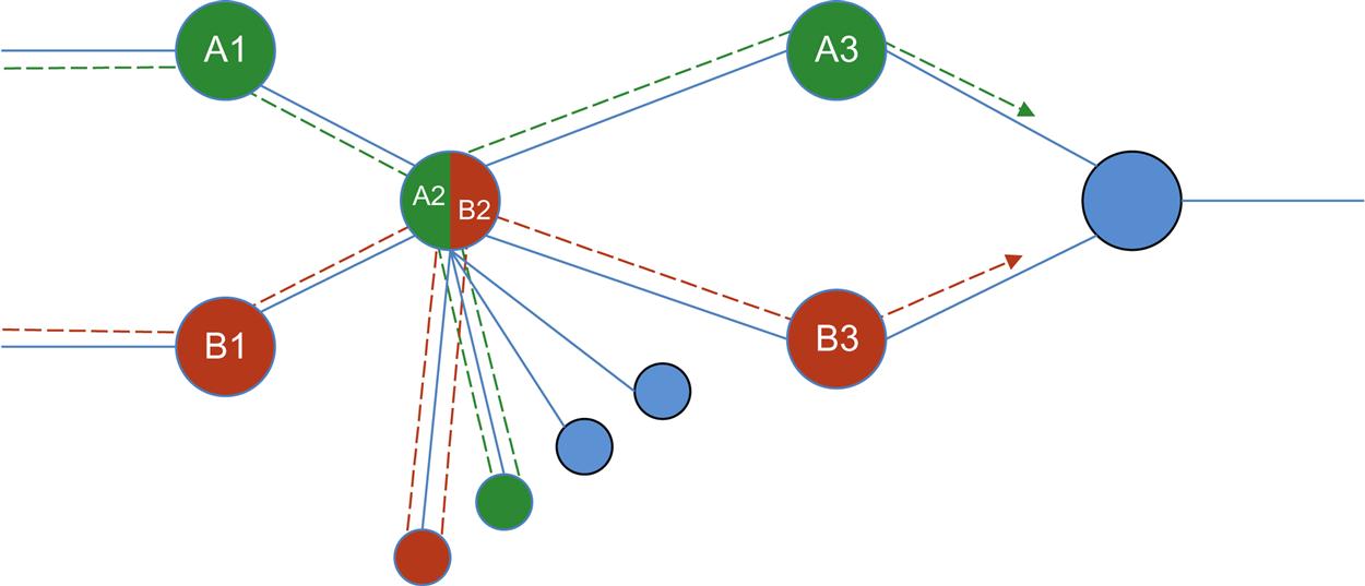
Fig. 2.7 demonstrates two service chains, A (A1, A2, A3) and B (B1, B2, B3), but also shows service function reuse service in that both chains traverse the same service function A2. In this figure we demonstrate how SFC should also provide the additional benefit of service component reuse where it makes sense. That is a single component/function can be utilized by more than one chain or path. Thus SFC will help an operator manage both the physical and logical separation of service functions, and at the same time, compressing together and optimizing resources.
Ultimately, the problem of configuration complexity will have to be solved outside of SFC.8 Note that by “configuration” we intend that more than the network path is configured. This is best expressed as the logical operation of the function itself when it is applied to a specific flow, affecting not only forwarding of the flow but also embedding state/policy dependencies. This can be accomplished through the use of common service models, which can eliminate or obscure the CLI of individual vendor implementations. This can be achieved using a standards-based (or de facto standard derived from open source) REST API call that is locally translated into a configuration. The next step here will likely involve some sort of evolution from vendor-specific to community-wide multivendor models. An early example of this normalization is the use of service models in the IETF NETMAP WG, or even The OpenDaylight project’s northbound API for SFC.
Note that service chaining still has to deal with architectural requirements around bidirectional flows. This is particularly true for stateful services where the restrictions imposed by highly integrated and loosely coupled services implicitly avoid these issues.
For stateless service functions, high availability will be realized through the “swarm” or “web-scale”9 approach.
This paradigm relies on orchestration and monitoring to eliminate failed members of a swarm of servers (ie, far more than a few servers) that scale to handle demand and simple load distribution. The collection of servers is either dictated in overlay network directives through central control, or managed inline. In the latter case, the abstraction between chain-and-path and function-and-instance are critical to scale.
For stateful service functions (eg, proxy services: any service that maps one communication session to another and thus has the reverse mapping state or monitors the status of a session in order to trigger some action), traditional HA mechanisms can be leveraged. These have traditionally been active/active or active/passive, 1:1 or 1:N, and with or without heartbeat failure detection.
Admittedly, traditional stateful function redundancy schemes have a cost component to be considered as well.
These traditional mechanisms have been labeled “weak” by recent academic work10 (or at least “nondeterministic” regarding the state synchronization, which can lead to session loss on failover). Potential mitigation techniques for “nondeterministic state sharing” have their own potential costs in delay and overall scale (eg, requirements to write to queues instead of directly to/from NIC, freezing the VM to snapshot memory) that need to be balanced.
New system design techniques such as those used in high scale distributed systems can be used to decouple these applications from a direct linkage to their state store (common store for worker threads) or their backup (if the state store is necessarily “local” by design), potentially enabling the web-scale availability model while reducing cost.11 This “nonmigratory” HA, like the recommendations to solve determinism problems in other schemes, assumes a rewrite of code in the transition from appliance to VM providing an opportunity to improve HA.
The traditional stateful HA approaches often include a scheme to appear as a single addressable network entity, thus masking their internal complexities (an abstraction that collapses detail).
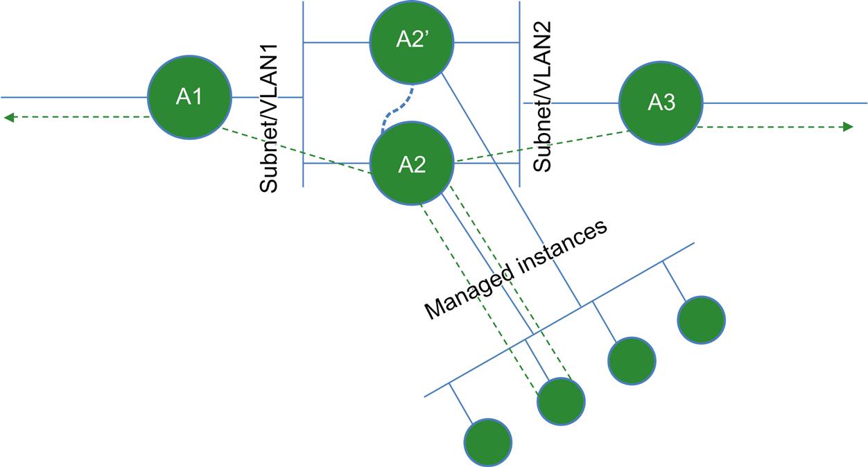
In Fig. 2.8, the service chain “A” is bidirectional and the function A2 is stateful and elastic. The service path for both the forward and reverse direction for a flow distributed by A2 to a virtual instance of its function must transit the same instance. Here A2 is shown as an HA pair with A2′.
To some degree, SFC might actually provide relief for common network operational problems through limited geographical service function or service path redundancy. The seemingly requisite distribution function whether centralized or locally available, may ultimately be leveraged to allow operational flexibility (eg, A/B software upgrade schemes or “live migration”).
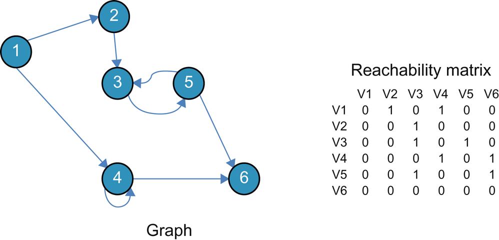
Ultimately, our view of a “chain” has to change from a linear concept to that of a “graph” (Fig. 2.9) whose vertices are service functions and edges can be IP or overlay connectivity—with less focus on the network connectivity and more on the relationship of the functions.
Varying Approaches to Decomposition
As we transition from the tightly coupled, through loosely coupled and on to full virtualization, it is important to note that different vendors may chose widely varying decomposition, scale, and packaging strategies to a service.
While the “base use case” (referenced in Chapter 1: Network Function Virtualization) is an “atomic” function that does not decompose (it may “multi-thread” to scale), and is thus relatively simple, some integrated service platforms are far more complex and potentially decompose-able.
Consumers and vendors often refer to this decomposition as creating “micro services” allowing them to either sell/consume a service in a formerly bundled “macro service” (eg, GiLAN may have an integrated NAT or Firewall service, which can now be “parted out” into a service chain) independently, allowing “best of breed” consumption. However, true “micro services” go beyond decomposition to the function/service level and can approach the process/routine level as an enabler of software agility, which we will touch on in a later chapter.
This is particularly well illustrated in the area of mobility with the GiLAN and vIMS (both of which we pointed to in Chapter 1: Network Function Virtualization, as a service that was well on its way to virtualization prior to the NFV mandate, and thus “low hanging fruit”).
For its part, the GiLAN decomposes into more readily-identifiable services/atoms IMS is a much more interesting study.
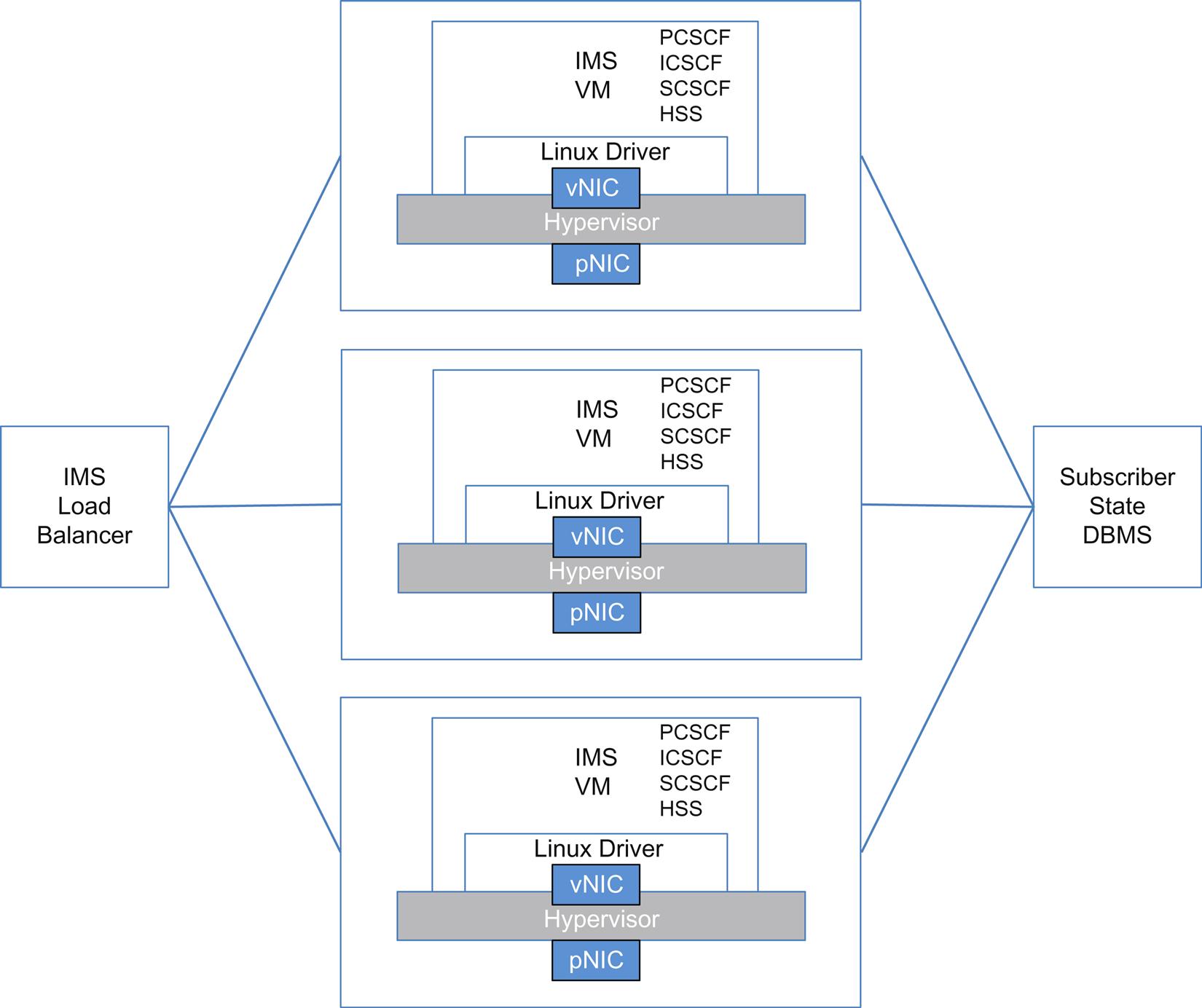
In a 2014 IEEE paper on cloudified IMS,12 the authors propose three possible solutions/implementation designs to address the scale requirements of a cloud implementation of IMS: a one-to-one mapping (or encapsulation of existing functionality, see Fig. 2.10), a split into subcomponents (completely atomic) and a decomposition with some functions merged. Each of these architectures preserves (in one way or another) the interfaces of the traditional service with minimal alteration to messaging to preserve interoperability with existing/traditional deployments.
These views illustrate the complexity involved and decision making in decomposing highly integrated functions that make a service—outside of the mechanisms used to chain the components together (the networking piece)!
In the one-to-one mapping, each function of a traditional IMS would be placed in its own VM (they do not have to be in the same host, this is a simplification). Note that some of the functions are stateful (and some are not). In this decomposition, 3GPP defines the discovery, distribution, and scaling of the individual functions.
In the split decomposition, each function has a function specific load balancer (Fig. 2.11). In this imagining, each function is rendered into a stateless worker thread (if it is not already stateless) in a container, with any shared state for the function being moved to shared memory. Even the load balancing is stateless, though it has its own complexities (it has to implement the 3GPP interfaces that the function would traditionally present).
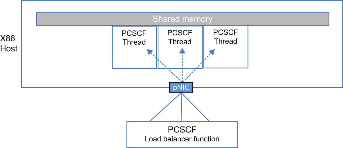
The last decomposition (Fig. 2.12) combines a subset of functions in the same VM (as threads) to reduce communication costs between them. It also removes the state in a common webscale fashion into a back-end database and replaces function-specific load balancing with a simple proxy (the proxy has to support one of the traditional IMS interfaces, Mw).
These choices in decomposition were the grist of some debate in the ETSI work, and ultimately were left undefined (with respect to how they would be managed and orchestrated) in their early work (see Chapter 3: ETSI NFV ISG).
Ultimately, many of the scale techniques use architectures that work within the limits of the von Neumann architecture that dominates COTS compute. We pick up on this theme in Chapter 7, The Virtualization Layer—Performance, Packaging, and NFV and Chapter 8, NFV Infrastructure—Hardware Evolution and Testing.
Metadata
Metadata is literally “data about data.” It is a context pertinent to a set of data.
Arguably, metadata might be more critical to the success of SFC than the creation of service overlays for virtual functions.
It is possible to create a service represented by a chain of service functions that do not need to pass any information, just as you might be able to create a service chain without an overlay—but these mechanisms (service overlay and metadata) are powerful and compelling.
Examples of compelling metadata include13:
• Forwarding information (such as VRF): the ingress VRF of the packet on the first classifier. Using this encoded VRF the last node in the chain can place the (post service(s)) packets into the right forwarding context. This way the service chain is “vrf enabled” without the service participating in the routing topology, and there is no need to return the packets, after chaining, to the original classifier
• Application ID: if the first classifier knows the application (from direct classification, or from an external source such as a VM manager), that application can be carried as metadata in an SFC-specific header. For example, the classifier imposes a value that indicates that the packet belong to “Oracle.” The firewall now no longer has to try to figure out if packets are “Oracle” or not, and can permit/deny based on the preclassified context. This model gets even more powerful when extended to services: they can update contexts as well and share it amongst themselves.
• External information about a flow: for example, the policy and charging rules function (PCRF) subscriber information can be encoded in the data plane. The services can use this context to apply subscriber-aware policy without having to participate in the policy/control planes.
Metadata may be “imputed”—derived from the flow itself. A ready example would be performance data, wherein the functions can compute elapsed time in transit from function to function as well as across function (detailed, in-band performance).14
Metadata can be carried both inline and out-of-band. Inline carriage will require the addition, in some form, to the packet format—which the IETF is struggling with in its SFC work group (and we cover in Chapter 4: IETF Related Standards: NETMOD, NETCONF, SFC and SPRING).
Out-of-band models are present in the security and mobility spaces via PCRF (Radius/Diameter) and IF-MAP. These schemes generally provide relief from the need to extend the packet header with metadata fields, but come with their own challenges.
• Out-of-band systems place a tax on the service function developer—the inclusion of a metadata exchange client.
• An out-of-band system design has to worry about the transaction rate (scale) on both client and server and the transaction RTT (delay). This can lead into an excursion into placement algorithms for the MAP servers and the use of caching on the client functions (with the associated problems of caching metadata—eg, staleness).
Even though mobility solutions use out-of-band today, some applications like mobile traffic acceleration (payments, fraud detection, and so forth) require interactions outside the data plane that are problematic as the flows are short lived and by the time the policy/metadata is fetched, the flow has already ended. For such an application, operators and vendors alike are looking to inline metadata.
If inline metadata is useful in environments that already have out-of-band models, it might be extended in a way that subsumes the role of the PCRF and charging interface interactions (trading space for metadata in a packet header for a decrease in the number of interactions).
To accommodate inline metadata, a number of service header modifications have been proposed at the IETF that impose inline changes to packet formats to include what is in essence, a unique identifier for a service flow. This approach has a few issues of its own.
The primary issue is the global uniqueness of a metadata identifier. How is this configured, implemented and more importantly, coordinated between multivendor devices?
A secondary issue is more philosophical; mainly that one of the potential advantages to SFC is to take an approach that mimics how VMs are implemented in environments where they are unaware that they are virtual. The need to understand metadata could break this illusion.
Metadata can be signaled/imposed by the application, imposed by a proxy (like a media services proxy that does lightweight DPI by snooping signaling protocols, or implicitly by network based application recognition (DPI). It can also be associated a priori with the classifier at the ingress of the SFC by a management and orchestration system.
To implement out-of-band metadata, a methodology (client, server, and protocol) and design will need to be determined and either an association of a metadata key with some preexisting packet header identifier such as an MPLS ingress label or a GRE tunnel cookie made. Presignaling is required to establish and connect service chains, as mappings between the functions need to be established with something that maintains the cookie-to-flow mapping (a map/policy/metadata server system). The obvious downsides to this scheme are seen in its maintenance and management (eg, session scale on the metadata server, transaction loop timing limits between server and client, local caching to abate the loop with subsequent cache coherency maintenance, and imbedding the selected client15).
What Can You Do with SFC?
The network edge environment may ultimately evolve to a distributed data center paradigm for services when the aforementioned problems are solved.
SFC enables the disaggregation of the service offering to span a larger, more loosely arranged topology. This topology might include explicitly dedicated devices, combined or “compound” units, or even be decomposed into smaller units that can create the service. The point is to better match operational needs through flexibility, while at the same time optimizing for cost.
Many operators are moving from highly integrated BNG/BRAS functions within dedicated and proprietary hardware-based edge routers in the Metro to virtualized deployments in a Regional Data Center. This sometimes exists within the Metro Point of Presence as a small rack of compute and storage. Some came to the realization of efficiencies of such solutions when they first explored the virtualization of Layer 3 Customer Premise Equipment (CPE) functions. These deployments had their own set of economic and agility related incentives for the operator (Fig. 2.13), but still lent themselves to other types of operations. This is the beauty of new technologies: sometimes we discover new uses for them only after we start playing with them.
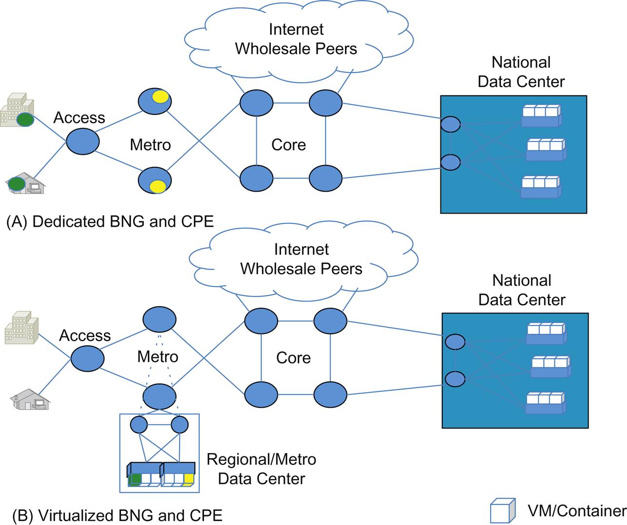
For example, Telefonica has proposed a Proof of Concept that has a software based Broadband Residential Access Server (BRAS) in the ETSI NFV WG. This soft BRAS is described with a limited set of functions: QinQ termination, Longest Prefix Match routing, GRE tunnel support (to enable wholesale services), and MPLS tunnel support that allows for optimized forwarding within their network.16
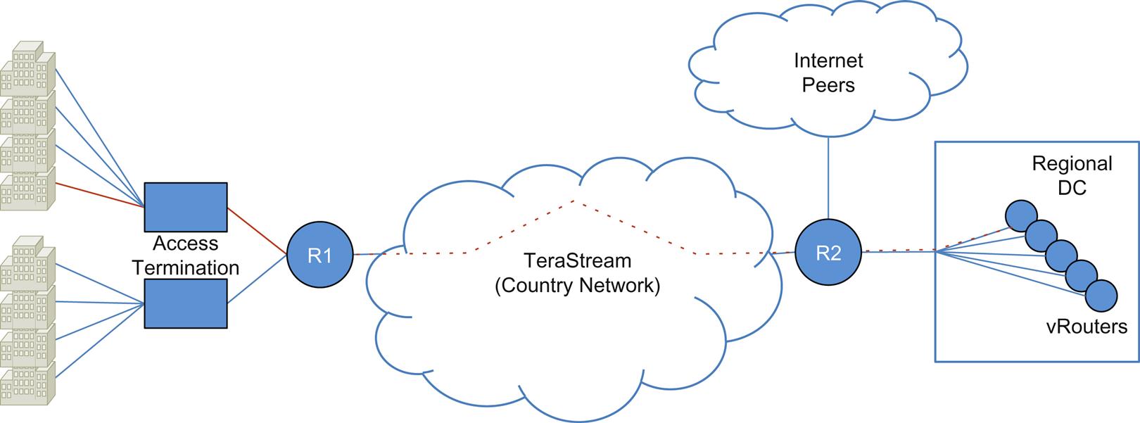
Practical and working examples of a vVPN function exist as well. These vVPN offers are described as a cloud-based VPN services and were first described in places like the early TeraStream17,18 project (Fig. 2.14) before any forum or standards body had studied NFV. This use case was driven by many of the same economic and operational motivations we described earlier.
It should be pointed out that while both services contain NFV and service chains, both utilize fundamentally different approaches to achieve what are ultimately similar goals.
This may be an indication that (at least for the early period of NFV/SFC) that the potential of any solution applied to one use case may or may not apply within the context of another, or the fact that one approach may not be “best” for all of NFV.
Service function reuse, and flexibility of service definition is critical to developing a common set of technologies that can apply broadly to problems we will encounter in this space.
The CloudVPN project provides the more traditional view of the migration of business services using virtualized functions. Since it evolved before any standardization of SFC, the first implementation relies on orchestrated VLAN stitching to create the service function chain. This allowed the firewall service to remain separate from the vRouter/vPE service.
The positioning of the vRouter in the CloudVPN service at a regional data center requires the service be tunneled across the infrastructure using L2TPv3 tunnels. Here a simple service offering requires a vPE termination (VPN) with a virtual firewall (vFW) that provides NAT, Policy and IPSec/SSL remote access. More complex service offerings add vISE for BYOD service authentication and vWSA for enhanced web access.
This example demonstrates how virtualization can be exploited in new service offerings by injecting vFWs, virtual caches, or other virtualized functions into the service path (virtual managed services). It also shows how building more differentiated services on a common platform can be achieved by snapping these independent services functions together. Further, these services will scale more elastically and independently with demand, at least to the limit of available compute, network and to a lesser degree, available storage.
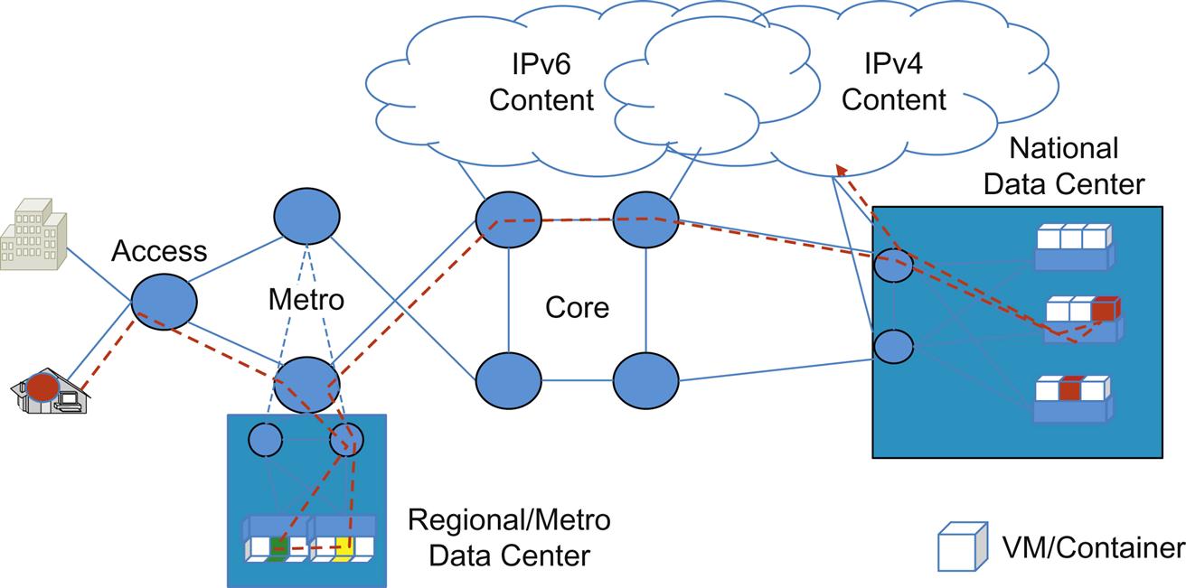
For “grandfathered” or declining services (eg, Fig. 2.15 IPv4aaS—an IPv6 migration strategy that consolidates the IPv4-to-v6 translation services), the virtualized function (NAT and various application gateway technologies) can be further concentrated by creating a service overlay. Note that this also illustrates dynamic service injection by appending an additional service element (address translation) to the end of the existing broadband connectivity service chain.
In the mobile network (a growing component of overall network usage), researchers have identified that the dominant component of traffic is data/video, and represents almost 70% of traffic in the LTE Evolved Packet Core network. The interesting observation they have made is that this traffic may not require the protections of GTP tunnels that provide circuit-like behaviors with QoS guarantees because the clients of such services do local application-layer buffering of content.19
Proposals are surfacing that reimagine solutions where this traffic is treated differently, reducing the signaling burden of the solution as well. This includes tunnel setup/teardown, which can be quite costly in terms of overall user experience impact.
In the mobile internet service environment, an offering for the GiLAN that uses an early form of service chaining to allow the connectivity illustrated earlier (in Fig. 2.5) to be realized in arbitrary topologies has been shown as a Proof of Concept.
The solution distributes the flow classification function (to eliminate this step as a bottleneck). Once classified, the flow subsequently follows a logical overlay using an imbedded service header (akin to the NSH proposal in the IETF SFC WG) by virtue of capabilities in the software forwarder (Cisco Systems’ VPP product, a version of which is open-sourced in fd.io (http://fd.io)) traversing a variety of scenario driven (treatment of HTTP depends on access technology as well as policy enforcement) service chains comprised of multivendor applications (including video optimization, firewall, self-service kiosk diversion to increase rating and NATP).
For some service offerings, NFV/SFC will allow a step-wise deployment scenario potentially starting with remote, virtualized functions, but ultimately leading to the placement of dedicated, integrated equipment or a regional/co-located compute pod. Also in terms of legacy service migration, or “cap and grow” strategies where existing equipment must be capped, and virtualized versions of the services those devices provided, NFV/SFC will be capable of coexisting in these scenarios. This is shown in Fig. 2.16.
In Fig. 2.16A, the new service (eg, expansion of a VPN service offering) could originally be realized in a new market from a virtual function or (service chain of functions) in an existing on-net facility (eg, National or Regional DC). The provider could lease circuits to a colocation facility in-market and could optionally colocate the virtualized functions there if delay was an issue, in addition to basic network equipment. Service up-take and corresponding increases in revenue could justify Fig. 2.16B. Here the network circuits and other resources become dedicated, and colocation of the service might be required and even potentially dedicated. In this case, integrated high-throughput service devices might be deployed but depend on the overall strategy an operator wishes to take here. For examples, from an operational perspective, this could be driven solely by a cost/space/power equation. However, other factors such as regulatory restrictions, might result in different choices.
Though these fledgling deployments are not all directly illustrative of SFC (more so, NFV orchestration, OSS integration and elasticity), the architectural shift to move compute and storage closer to the customer can be exploited in new service offerings by injecting vFWs, virtual caches, or other virtualized functions into the service path (building more differentiated services on a common platform—Fig. 2.15). Further, these services will scale more easily (and independently) with demand (at least to the limit of available compute).
The larger savings from this operating paradigm come with changes in the operational model. These come in the near term via a shift towards DevOps-driven automation and self-service service provisioning in conjunction with NFV (reducing the cycle time to realize or alter a service), and in the long term via changes in the OSS and its cost structures.20
The dynamic and elastic nature of SFC is aided by evolving the use of embedded analytics in the services, virtual service platforms, and OSS/Orchestration. We will visit this in more detail in a later chapter.
Aside from this, one of the big opportunities in service creation via NFV/SFC is the ability to reimagine and simplify services. Many operators are looking at the plethora of features that vendors have provided at their and other operator’s behest in existing equipment, to create new differentiated services.
Many realized that on average, they used a small portion of the overall software feature set in tightly integrated equipment, and saw the larger feature set as a potentially larger surface for security problems and general software defects (the reality of this fear depends on the vendor implementation).
Some have discovered that their more specialized service offerings, which required a high degree of feature were an economic and operational drag, did not generate enough revenue to justify the specialization (and created a barrier of entry to new vendors). This introspection allows for simplification.
Similarly, opportunities exist for many vendors who are in their “first-generation” of service function virtualization, where they simply replicate their hardware-centric models in software.
In most cases, this generation is implemented as one-service-per-VM, and performance is, as one would expect: far less than it was on the dedicated hardware.
For example, a new security service offering today might envision separate VMs for a vFW plus a vIDS and perhaps other modules as well. Going forward, these separate VMs may be homogenized in a next-generation security appliance as dynamically loadable modules within the same product—optimized for a virtual environment.
It may be that current industry virtual product delivery methodologies are driven by customer consumption capabilities (the existing operation requires that the virtual service functions replacing the integrated solution conform to their existing tooling).
In this case, until the customer’s operations and management systems can accommodate these “re-imaginings,” they could be stuck in this “first-generation” or “emulation” mode.
Most vendors are moving quickly to support second-generation functions, spurred both by the customer demand for new paradigms and the entrance of new competitors (who target the market with initially lower feature but higher performance variants). The future is interesting and bright in this space.
Logical Limits
The speed of light
There are some practical bounds on SFC, even if the point is to remove topology constraints and other physical dependencies.
The three biggest limits will be the complexity of troubleshooting a very topologically diverse deployment of functions that compose a chain, achieving the overall Service Level Agreement (SLA) requirements for the service itself, and finally the fact that the underlying infrastructure may have resource/capacity limits.
It is possible that High Availability strategies for NFV/SFC might incorporate the use of service function elements in far-flung geographies, but transport latency (eg, the speed of light in a glass fiber) ultimately might bind how far afield an operator might realistically allow a service path to wander.21
There may be mitigating factors in either the nature of the service or where traffic may ultimately be exiting/sinking in the network and then return. These can be due to existing equipment or other resource availability, or even regulatory requirements.
For our example, in Fig. 2.17 if an operator created a service chain (“foo”) with functions (“bar” and “baz”) that should be optimized geographically, but not constrained geographically, we would expect that the functions originally would all be coresident in Washington to serve traffic originating in Washington.
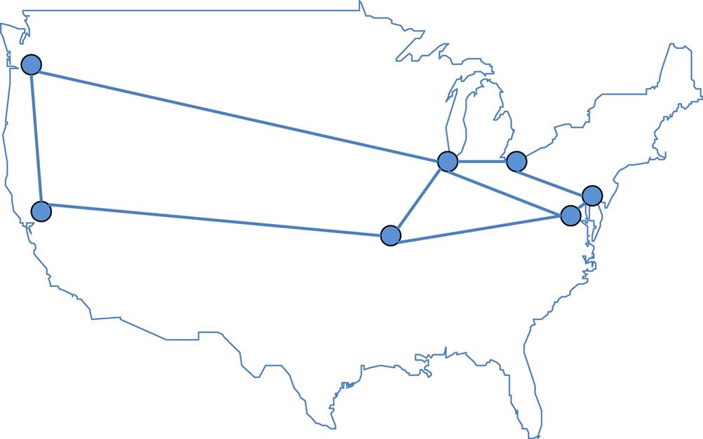
If there were no constraints, it “might” be possible to meet reasonable delay SLA using HA scenarios wherein the “foo” service can either be moved as a whole (via path redundancy, where the “bar” and “baz” functions are relocated to another service center/PoP) or in part (where traffic for a single function “bar” loops to and returns from an another service center/PoP.
But, in general, the delays due to propagation assuming a best case transmission, appreciate quickly and so the options in these cases can be rather limited (Fig. 2.18):
• If there were a “bar” function failure and the operator allowed atomic replacement “bar” in Washington with “bar” in Philadelphia, the overall impact to delay in the service will be almost 3 ms (round-trip).
• If the provider allowed similar “bar” substitution with an instance of “bar” in Chicago, direct access would add almost 14.5 ms of delay, and indirect access (Washington to Philadelphia to Cleveland to Chicago) would add almost 20 ms of round-trip delay.22
• The West Coast (eg, Seattle) delay is obviously much worse.
Even if the eligible functions to fit a service chain were restricted to a “regional” scope, the variability in delay depending on the specific network path taken would have to be accommodated.
These examples make it clear, at least to us, that between the dynamics of service element instantiation (NFV) and SFC chain/path updates, the paradigm of “fail fast and fail hard” may make for the most manageable future services.
Granularity and extra vSwitch or network transitions
It may also be attractive to speculate on further reusability or economy in decomposing service functions into subcomponents that may be shared between service functions.
For instance, consider the abstraction of a compute routine that is highly specialized in doing encryption, hashing or other generic service.
The immediate trade-off in Fig. 2.19 is that both functions, broken into subfunctions so that they may share one of those subfunctions, will have to do at least one23 additional hypervisor hop. This could be worse if an additional network hop or hops results. Subsequent chains that included all three functions could also quickly become a multiplier of the effect. Consider that ultimately there is a practical limit to the decomposition of the functions imposed by the extra network transition(s) that is governed by the limits of the hypervisor, dock/container, network and storage technologies that are in use.
Standardization above the network layer
Some operators have environments where a very tight proximity of application and service function (eg, financial applications and firewall/IDS services) is desirable. These interactions are potentially conducive to inter-process communication or other optimizations that eliminate the network hop between containers/instances.
Switching between VMs above the hypervisor is being explored in both the netmap/vale and vhost-user projects (Chapter 7: The Virtualization Layer—Performance, Packaging, and NFV)—offering both common exploitable methodologies and performance impact mitigation (certainly performing better than the loop through a hypervisor/vSwitch).
Additionally, there are some “service functions” that might naturally evolve and connect at the application layer.
For example, a Platform as a Service (PaaS) development environment might contain some services—what some might term “endpoint services”—that are treated differently from the current notion in NFV/SFC. In this environment, the specifics of what we might refer to as the “currency” of the type or types of operations a service provides might be at the packet level or the application request level. The action or actions performed might be an application-level callback. In this environment, proximity is paramount (request transaction service examples include dependency monitoring or circuit-breaker services24).
Once the connection between functions moves above the network layer, it becomes transparent to the current concept of “network” service path. Inter-process communication or API/callback methodologies are further from standardization and potentially harder to monitor. As these become more common scenarios, the concept of NFV and SFC is likely to expand. While some of this behavior might be developed through proposed metadata extensions to the packet header in SFC (eg, a triggered callback by the presence of metadata), this is a fundamentally different type of “pipe” with potentially higher performance requirements than just simple network-level relay.
The capabilities of old stuff—The “brownfield” of dreams
Finally, any evolving technology might lead to hybrid deployments in which some of the elements are potentially more capable participants. This is particularly true for SFC in the case where an operator wants to leverage a combination of newer, virtualized service functions with legacy, integrated hardware elements.
This is sometimes referred to as a hybrid, or “brownfield” deployment versus a “greenfield” where everything is new. (Fig. 2.20 illustrates a potential “brownfield” reality.)

In our experience, the “greenfield” is quite rare and often left to academic research environments. For the more canonical case, a business might, for depreciation requirements and/or technical reasons such as throughput or power footprint optimization, wish to create such a hybrid environment.
In other more obvious cases, the operator simply wishes to “cap and grow” legacy, integrated hardware systems and instead deploy only virtualized versions of those elements—or a subset of their specific functions.
As we continue on, we will need to be able to describe these legacy elements as composite services in the management and planning of chains and paths so that better, and simpler planning and designs will be capable.
Because these hybrid systems may lack the capabilities and agility of pure-software solutions, it may make them incapable of fully participating in the evolving SFC without a proxy, but this is simply a design trade-off.
Such a proxy can have a varying level of complexity, depending on how much of the service overlay functionality it attempts to relay to the legacy service function. And over time, this hybrid approach will grow into one that does enjoy a majority of virtualized NFV/SFCs.
Common sense
It should go without saying, that not all network function applications backhaul or “burst” into any given cloud well. This goes hand-in-hand with the opportunity NFV/SFC presents to reimagine a service. For example, the current approach to DDoS mitigation service works well for distributed attacks, since the current concept of backhauling traffic to a virtualized “scrubber” can handle modest scale. However, backhaul of volumetric attacks that comprise data flows totaling in the 100s of Gbps, stress not only the scale out of the “scrubber” but also beg network efficiency questions such as if it was going to be dropped, then it was a waste to backhaul it.
This is an example of where NFV/SFV can be taken only so far. When you push any application towards physical/resource limits, things can break down. Keeping in mind that this example took today’s model of DDoS mitigation and basically virtualized it, a reimagination of the solution, perhaps distributing more functionality might be an appropriate and workable solution. NFV/SFC give a network operator the tools to do this.
NFV Without SFC
We have already glanced at the potential of PaaS and application level connectivity as a potential future architecture for NFV. In Chapter 7, The Virtualization Layer—Performance, Packaging, and NFV, we will explore the fact that more than one architectural solution is possible for NFV.
We will look at a container/VM hybrid vCPE solution that bypasses the host hypervisor for at least the networking component, and directly terminates pseudowires from the (largely residential) service access devices (CPE) to an environment built on UML26 containers (eg, micro-VMs), the solution provides a glimpse into a different take on the necessity of service chaining.
Designed to offload or augment a traditional BNG, this is an example where service chaining is perhaps unnecessary.
In this case, services were built out as per-customer “kernel as NFV.” One interesting side note on this is that it also created and exposed a programmable API that allowed its own developers to expand the environment quickly and easily.
The challenge of this model to both SFC and the ETSI NFV model (our next chapter) is that it provides a scalable, working solution without poll-mode drivers (which potentially makes the solution more energy efficient) and minimizes the traversal of the network boundary—based on the principle that once you have the packet in memory, it is most efficient to do as many operations (on it) as possible. By chaining VMs (or containers) to implement individual services, the packet has to be copied in and out of memory several times, regardless of the acceleration philosophy applied to minimize the delay this causes.
Services within the container may still use metadata, but its allocation and use is proprietary to the service designer/architect (much like the highly integrated devices that preceded the virtualization revolution).
In some ways these approaches may seem like less-tightly integrated models that provides an open API for service developers as well as the benefits from the elasticity of NFV and is more of a step toward the “micro-services” future.
Conclusion
At its very core, NFV/SFC is being pursued to address the service creation problems of the past. By virtualizing services, creating service overlays and passing metadata we are enabling the conversion away from integrated service solutions.
When combined with NFV, SFC allows a network operator to properly resource a service, function-by-function, exploiting the orchestration tooling and elasticity concepts maturing in Data Center operations today.
In pursuing NFV service solutions, the operator may benefit by simply deploying a service traditionally implemented on proprietary hardware but in a virtualized environment. However, further benefits may accrue from a reimagining of such a service so that it needs fewer features in its virtualized incarnation and in doing so, allow the vendor to implement the same functionality with a much smaller software set. This reimagination might result in better scale and improved operation of solutions, which may only be possible with an NFV/SFC-type solution.
To provide benefit, the SFC architecture must compensate for the advantages of a highly integrated service, including the ability to pass a context between the service functions in a service chain and surmount the configuration complexity that might arise from the use of disparate components.
While the examples we can cite of SFC do not yet incorporate the passing of a context or clue (as they were attempted prior to standardization of metadata passing within a service chain) we feel that over time, new applications will emerge that take advantage of this evolving feature.
SFC frees the operator from topology constraints, allowing them to leverage a logical overlay to instantiate services in remote markets without having to preplace dedicated equipment. This new-found agility is important and should not be underestimated. There are, however, potential limits to those freedoms, such as meeting existing SLAs.
The world is rarely a “greenfield” deployment for a network operator, and NFV/SFC efficacy may be limited by the capabilities of existing systems in “brownfield” deployments.
With variability and freedom comes complexity. To limit operational complexity, many operators may still construct service chains by deploying service functions in localized, “logical” line-ups rather than the physical pipelines of the past. These new solutions will take advantage of the function elasticity afforded by NFV.
Finally, some deployments are emerging that provide high performance NFV services by creating a service creation environment within a single virtual element—obviating the need for external chaining. Other services are also evolving that might require some sort connectivity above the network layer or be expressed as a de-composition that needs to be managed as a single function.
