
ENHANCING SURFACE DETAIL

Suppose we want to model an object with an irregular surface—like the bumpy surface of an orange, the wrinkled surface of a raisin, or the cratered surface of the moon. How would we do it? So far, we have learned two potential methods: (a) we could model the entire irregular surface, which would often be impractical (a highly cratered surface would require a huge number of vertices); or (b) we could apply a texture-map image of the irregular surface to a smooth version of the object. The second option is often effective. However, if the scene includes lights, and the lights (or camera angle) move, it becomes quickly obvious that the object is statically textured (and smooth), because the light and dark areas on the texture wouldn’t change as they would if the object was actually bumpy.
In this chapter we are going to explore several related methods for using lighting effects to make objects appear to have realistic surface texture, even if the underlying object model is smooth. We will start by examining bump mapping and normal mapping, which can add considerable realism to the objects in our scenes when it would be too computationally expensive to include tiny surface details in the object models. We will also look at ways of actually perturbing the vertices in a smooth surface through height mapping, which is useful for generating terrain (and other uses).
10.1BUMP MAPPING
In Chapter 7, we saw how surface normals are critical to creating convincing lighting effects. Light intensity at a pixel is determined largely by the reflection angle, taking into account the light source location, camera location, and the normal vector at the pixel. Thus, we can avoid generating detailed vertices corresponding to a bumpy or wrinkled surface if we can find a way of generating the corresponding normals.
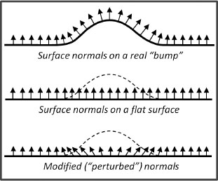
Figure 10.1
Perturbed normal vectors for bump mapping.
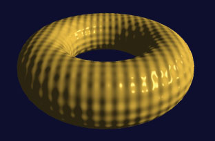
Figure 10.2
Procedural bump mapping example.
Figure 10.1 illustrates the concept of modified normals corresponding to a single “bump.”
Thus, if we want to make an object look as though it has bumps (or wrinkles, craters, etc.), one way is to compute the normals that would exist on such a surface. Then when the scene is lit, the lighting would produce the desired illusion. This was first proposed by Blinn in 1978 [BL78], and it became practical with the advent of the capability of performing per-pixel lighting computations in a fragment shader.
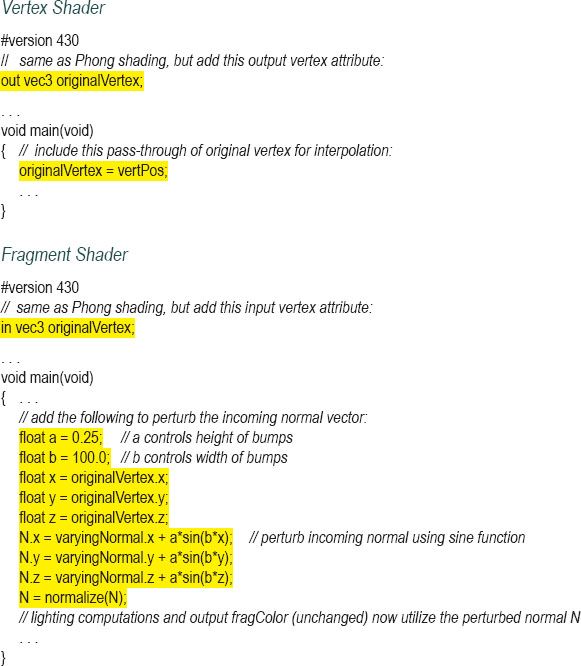
An example is illustrated in the vertex and fragment shaders shown in Program 10.1, which produces a torus with a “golf-ball” surface as shown in Figure 10.2. The code is almost identical to what we saw previously in Program 7.2. The only significant change is in the fragment shader—the incoming interpolated normal vectors (named “varyingNormal” in the original program) are altered with bumps calculated using a sine wave function in the X, Y, and Z axes applied to the original (untransformed) vertices of the torus model. Note that the vertex shader therefore now needs to pass these untransformed vertices down the pipeline.
Altering the normals in this manner, with a mathematical function computed at runtime, is called procedural bump mapping.
Program 10.1 Procedural Bump Mapping
10.2NORMAL MAPPING
An alternative to bump mapping is to replace the normals using a lookup table. This allows us to construct bumps for which there is no mathematical function, such as the bumps corresponding to the craters on the moon. A common way of doing this is called normal mapping.
To understand how this works, we start by noting that a vector can be stored to reasonable precision in three bytes, one for each of the X, Y, and Z components. This makes it possible to store normals in a color image file, with the R, G, and B components corresponding to X, Y, and Z. RGB values in an image are stored in bytes and are usually interpreted as values in the range [0..1], whereas vectors can have positive or negative component values. If we restrict normal vector components to the range [˗1..+1], a simple conversion to enable storing a normal vector N as a pixel in an image file is:

Normal mapping utilizes an image file (called a normal map) that contains normals corresponding to a desired surface appearance in the presence of lighting. In a normal map, the vectors are represented relative to an arbitrary plane X-Y, with their X and Y components representing deviations from “vertical” and their Z component set to 1. A vector strictly perpendicular to the X-Y plane (i.e., with no deviation) would be represented (0,0,1), whereas non-perpendicular vectors would have non-zero X and/or Y components. We use the above formulae to convert to RGB space; for example, (0,0,1) would be stored as (.5,.5,1), since actual offsets range [˗1..+1], but RGB values range [0..1].
We can make use of such a normal map through yet another clever application of texture units: instead of storing colors in the texture unit, we store the desired normal vectors. We can then use a sampler to look up the value in the normal map for a given fragment, and then rather than applying the returned value to the output pixel color (as we did in texture mapping), we instead use it as the normal vector.
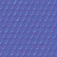
Figure 10.3
Normal mapping image file example [ME11].
One example of such a normal map image file is shown in Figure 10.3. It was generated by applying the GIMP normal mapping plugin [GI16] to a texture from Luna [LU16]. Normal-mapping image files are not intended for viewing; we show this one to point out that such images end up being largely blue. This is because every entry in the image file has a B value of 1 (maximum blue), making the image appear “bluish” if viewed.
Figure 10.4
Normal mapping examples.
Figure 10.4 shows two different normal map image files (both are built out of textures from Luna [LU16]) and the result of applying them to a sphere in the presence of Blinn-Phong lighting.
Normal vectors retrieved from a normal map cannot be utilized directly, because they are defined relative to an arbitrary X-Y plane as described previously, without taking into account their position on the object and their orientation in camera space. Our strategy for addressing this will be to build a transformation matrix for converting the normals into camera space, as follows.
At each vertex on an object, we consider a plane that is tangent to the object. The object normal at that vertex is perpendicular to this plane. We define two mutually perpendicular vectors in that plane, also perpendicular to the normal, called the tangent and bitangent (sometimes called the binormal). Constructing our desired transformation matrix requires that our models include a tangent vector for each vertex (the bitangent can be built by computing the cross product of the tangent and the normal). If the model does not already have tangent vectors defined, they could be computed. In the case of a sphere they can be computed exactly, as shown in the following modifications to Program 6.1:
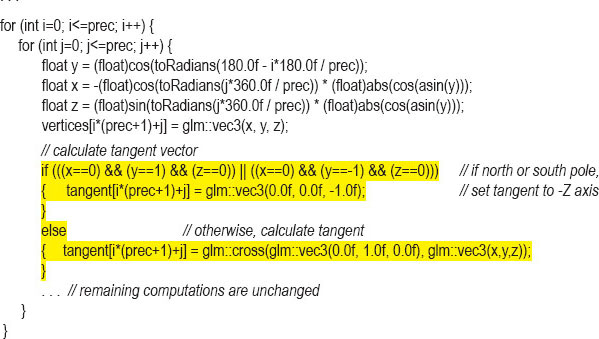
For models that don’t lend themselves to exact analytic derivation of surface tangents, the tangents can be approximated, for example by drawing vectors from each vertex to the next as they are constructed (or loaded). Note that such an approximation can lead to tangent vectors that are not strictly perpendicular to the corresponding vertex normals. Implementing normal mapping that works across a variety of models therefore needs to take this possibility into account (our solution will).
The tangent vectors are sent from a buffer (VBO) to a vertex attribute in the vertex shader, as is done for the vertices, texture coordinates, and normals. The vertex shader then processes them the same as is done for normal vectors, by applying the inverse-transpose of the MV matrix and forwarding the result down the pipeline for interpolation by the rasterizer and ultimately into the fragment shader. The application of the inverse transpose converts the normal and tangent vectors into camera space, after which we construct the bitangent using the cross product.
Once we have the normal, tangent, and bitangent vectors in camera space, we can use them to construct a matrix (called the “TBN” matrix, after its components) which transforms the normals retrieved from the normal map into their corresponding orientation in camera space relative to the surface of the object.
In the fragment shader, the computing of the new normal is done in the calcNewNormal() function. The computation in the third line of the function (the one containing dot(tangent, normal)) ensures that the tangent vector is perpendicular to the normal vector. A cross product between the new tangent and the normal produces the bitangent.
We then create the TBN as a 3×3 mat3 matrix. The mat3 constructor takes three vectors and generates a matrix containing the first vector in the top row, the second vector in the middle row, and the third in the bottom row (similar to building a view matrix from a camera position—see Figure 3.13).
The shader uses the fragment’s texture coordinates to extract the normal map entry corresponding to the current fragment. The sampler variable “normMap” is used for this, and in this case is bound to texture unit 0 (note: the C++/OpenGL application must therefore have attached the normal map image to texture unit 0). To convert the color component from the stored range [0..1] to its original range [-1..+1], we multiply by 2.0 and subtract 1.0.
The TBN matrix is then applied to the resulting normal to produce the final normal for the current pixel. The rest of the shader is identical to the fragment shader used for Phong lighting. The fragment shader is shown in Program 10.2 and is based on a version by Etay Meiri [ME11].
A variety of tools exist for developing normal map images. Some image editing tools, such as GIMP [GI16] and Photoshop [PH16], have such capabilities. Such tools analyze the edges in an image, inferring peaks and valleys, and produce a corresponding normal map.
Figure 10.5 shows a texture map of the surface of the moon created by Hastings-Trew [HT16] based on NASA satellite data. The corresponding normal map was generated by applying the GIMP normal map plugin [GP16] to a black and white reduction also created by Hastings-Trew.
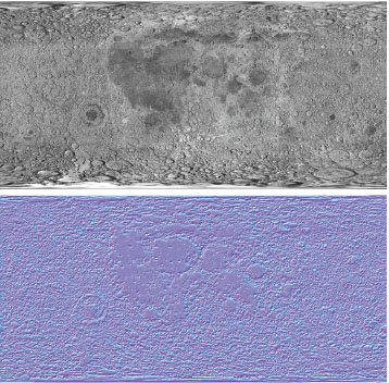
Figure 10.5
Moon, texture and normal map.
Program 10.2 Normal Mapping Fragment Shader
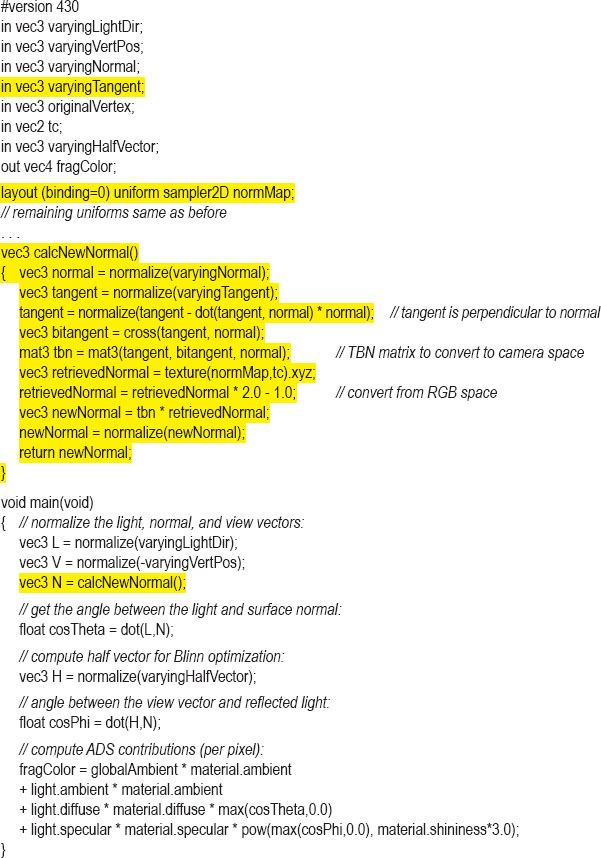
Figure 10.6
Sphere textured with moon texture (left) and normal map (right).
Figure 10.6 shows a sphere with the moon surface rendered in two different ways. On the left, it is simply textured with the original texture map; on the right, it is textured with the image normal map (for reference). Normal mapping has not been applied in either case. As realistic as the textured “moon” is, close examination reveals that the texture image was apparently taken when the moon was being lit from the left, because ridge shadows are cast to the right (most clearly evident in the crater near the bottom center). If we were to add lighting to this scene with Phong shading, and then animate the scene by moving the moon, the camera, or the light, those shadows would not change as we would expect them to.
Furthermore, as the light source moves (or as the camera moves), we would expect many specular highlights to appear on the ridges. But a plain textured sphere such as at the left of Figure 10.6 would produce only one specular highlight, corresponding to what would appear on a smooth sphere, which would look very unrealistic. Incorporation of the normal map can improve the realism of lighting on objects such as this considerably.
If we use normal mapping on the sphere (rather than applying the texture), we obtain the results shown in Figure 10.7. Although not as realistic (yet) as standard texturing, it now does respond to lighting changes. The first image is lit from the left, and the second is lit from the right. Note the blue and yellow arrows showing the change in diffuse lighting around ridges and the movement of specular highlights.
Figure 10.8 shows the effect of combining normal mapping with standard texturing in the presence of Phong lighting. The image of the moon is enhanced with diffuse-lit regions and specular highlights that respond to the movement of the light source (or camera or object movement). Lighting in the two images is from the left and right sides respectively.
Figure 10.7
Normal map lighting effects on the moon.
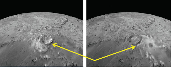
Figure 10.8
Texturing plus normal mapping, with lighting from the left and right.
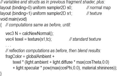
Our program now requires two textures—one for the moon surface image, and one for the normal map—and thus two samplers. The fragment shader blends the texture color with the color produced by the lighting computation as shown in Program 10.3, using the technique described previously in Section 7.6.
Program 10.3 Texturing plus Normal Map
Interestingly, normal mapping can benefit from mipmapping, because the same “aliasing” artifacts that we saw in Chapter 5 for texturing also occur when using a texture image for normal mapping. Figure 10.9 shows a normal-mapped moon, with and without mipmapping. Although not easily shown in a still image, the sphere at the left (not mipmapped) has shimmering artifacts around its perimeter.
Anisotropic filtering (AF) works even better, reducing sparkling artifacts while preserving detail, as illustrated in Figure 10.10 (compare the detail on the edge along the lower right). A version combining equal parts texture and lighting with normal mapping and AF is shown alongside, in Figure 10.11.
The results are imperfect. Shadows appearing in the original texture image will still show on the rendered result, regardless of lighting. Also, while normal mapping can affect diffuse and specular effects, it cannot cast shadows. Therefore, this method is best used when the surface features are small.
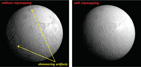
Figure 10.9
Normal mapping artifacts, corrected with mipmapping.
Figure 10.10
Normal mapping with AF.
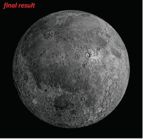
Figure 10.11
Texturing plus normal mapping with AF.
10.3HEIGHT MAPPING
We now extend the concept of normal mapping—where a texture image is used to perturb normals—to instead perturb the vertex locations themselves. Actually modifying an object’s geometry in this way has certain advantages, such as making the surface features visible along the object’s edge and enabling the features to respond to shadow-mapping. It can also facilitate building terrain, as we will see.
A practical approach is to use a texture image to store height values, which can then be used to raise (or lower) vertex locations. An image that contains height information is called a height map, and using a height map to alter an object’s vertices is called height mapping. Height maps usually encode height information as grayscale colors: (0,0,0) (black) = low height, and (1,1,1) (white) = high height. This makes it easy to create height maps algorithmically or by using a “paint” program. The higher the image contrast, the greater the variation in height expressed by the map. These concepts are illustrated in Figure 10.12 (showing a randomly generated map) and Figure 10.13 (showing a map with an organized pattern).
The usefulness of altering vertex locations depends on the model being altered. Vertex manipulation is easily done in the vertex shader, and when there is a high level of detail in the model vertices (such as in a sphere with sufficiently high precision), this approach can work well. However, when the underlying number of vertices is small (such as the corners of a cube), rendering the object’s surface relies on vertex interpolation in the rasterizer to fill in the detail. When there are very few vertices available in the vertex shader to perturb, the heights of many pixels would be interpolated rather than retrieved from the height map, leading to poor surface detail. Vertex manipulation in the fragment shader is, of course, impossible because by then the vertices have been rasterized into pixel locations.
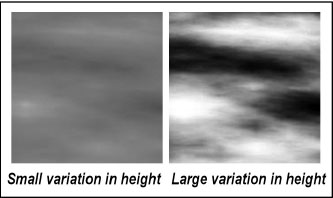
Figure 10.12
Height map examples.
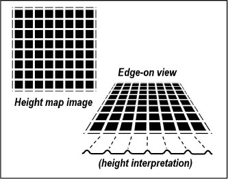
Figure 10.13
Height map interpretation.
Program 10.4 shows a vertex shader that moves the vertices “outward” (i.e., in the direction of the surface normal) by multiplying the vertex normal by the value retrieved from the height map and then adding that product to the vertex position.
Program 10.4 Height Mapping in Vertex Shader
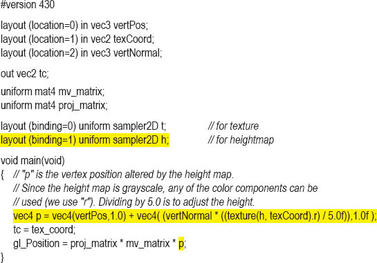
Figure 10.14 shows a simple height map (top left) created by scribbling in a paint program. A white square is also drawn in the height map image. A green-tinted version of the height map (bottom left) is used as a texture. When the height map is applied to a rectangular 100x100 grid model using the shader shown in Program 10.4, it produces a sort of “terrain” (shown on the right). Note how the white square results in the precipice at the right.
Figure 10.15 shows another example of doing height mapping in a vertex shader. This time the height map is an outline of the continents of the world [HT16]. It is applied to a sphere textured with a blue-tinted version of the height map (see top left—note the original black-and-white version is not shown), lit with Blinn-Phong shading using a normal map (shown at the lower left) built using the tool SS_Bump_Generator [SS16]. The sphere precision was increased to 500 to ensure that there are enough vertices to render the detail. Note how the raised vertices affect not only the lighting, but also the silhouette edges.
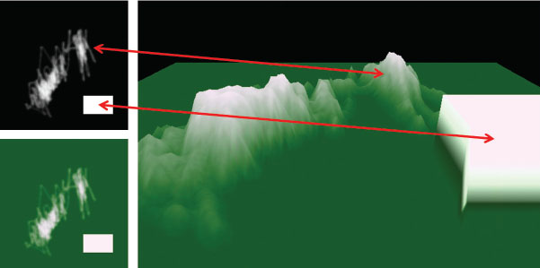
Figure 10.14
Terrain, height-mapped in the vertex shader.
Figure 10.15
Vertex shader-based height mapping, applied to a sphere.
The rendered examples shown in Figure 10.14 and Figure 10.15 work acceptably because the two models (grid and sphere) have a sufficient number of vertices to sample the height map values. That is, they each have a fairly large number of vertices, and the height map is relatively coarse and adequately sampled at a low resolution. However, close inspection still reveals the presence of resolution artifacts, such as along the bottom left edge of the raised box at the right of the terrain in Figure 10.14. The reason that the sides of the raised box don’t appear perfectly square, and include gradations in color, is because the 100x100 resolution of the underlying grid cannot adequately align perfectly with the white box in the height map, and the resulting rasterization of texture coordinates produces artifacts along the sides.
The limitations of doing height mapping in the vertex shader are further exposed when trying to apply it with a more demanding height map. Consider the moon image shown back in Figure 10.5. Normal mapping did an excellent job of capturing the detail in the image (as shown previously in Figure 10.9 and Figure 10.11), and since it is grayscale, it would seem natural to try applying it as a height map. However, vertex-shader-based height mapping would be inadequate for this task, because the number of vertices sampled in the vertex shader (even for a sphere with precision=500) is small compared to the fine level of detail in the image. By contrast, normal mapping was able to capture the detail impressively, because the normal map is sampled in the fragment shader, at the pixel level.
We will revisit height mapping later in Chapter 12 when we discuss methods for generating a greater number of vertices in a tessellation shader.
SUPPLEMENTAL NOTES
One of the fundamental limitations of bump or normal mapping is that, while they are capable of providing the appearance of surface detail in the interior of a rendered object, the silhouette (outer boundary) doesn’t show any such detail (it remains smooth). Height mapping, if used to actually modify vertex locations, fixes this deficiency, but it has its own limitations. As we will see later in this book, sometimes a geometry or tessellation shader can be used to increase the number of vertices, making height mapping more practical and more effective.
We have taken the liberty of simplifying some of the bump and normal mapping computations. More accurate and/or more efficient solutions are available for critical applications [BN12].
Exercises
10.1Experiment with Program 10.1 by modifying the settings and/or computations in the fragment shader and observing the results.
10.2Using a paint program, generate your own height map and use it in Program 10.4. See if you can identify locations where detail is missing as the result of the vertex shader being unable to adequately sample the height map. You will probably find it useful to also texture the terrain with your height map image file as shown in Figure 10.14 (or with some sort of pattern that exposes the surface structure, such as a grid) so that you can see the hills and valleys of the resulting terrain.
10.3(PROJECT) Add lighting to Program 10.4 so that the surface structure of the height-mapped terrain is further exposed.
10.4(PROJECT) Add shadow-mapping to your code from Exercise 10.3 so that your height-mapped terrain casts shadows.
References
[BL78] |
J. Blinn, “Simulation of Wrinkled Surfaces,” Computer Graphics 12, no. 3 (1978): 286–292. |
[BN12] |
E. Bruneton and F. Neyret, “A Survey of Non-Linear Pre-Filtering Methods for Efficient and Accurate Surface Shading,” IEEE Transactions on Visualization and Computer Graphics 18, no. 2 (2012). |
[GI16] |
GNU Image Manipulation Program, accessed October 2018, http://www.gimp.org |
[GP16] |
GIMP Plugin Registry, normalmap plugin, accessed October 2018, https://code.google.com/archive/p/gimp-normalmap |
[HT16] |
J. Hastings-Trew, JHT’s Planetary Pixel Emporium, accessed October 2018, http://planetpixelemporium.com/ |
[LU16] |
F. Luna, Introduction to 3D Game Programming with DirectX 12, 2nd ed. (Mercury Learning, 2016). |
[ME11] |
E. Meiri, OGLdev tutorial 26, 2011, accessed October 2018, http://ogldev.atspace.co.uk/index.html |
[PH16] |
Adobe Photoshop, accessed October 2018, http://www.photoshop.com |
[SS16] |
SS Bump Generator, accessed October 2018, https://sourceforge.net/projects/ssbumpgenerator |