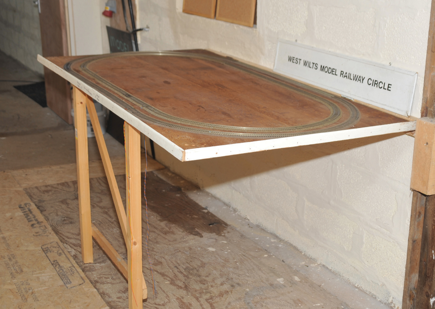
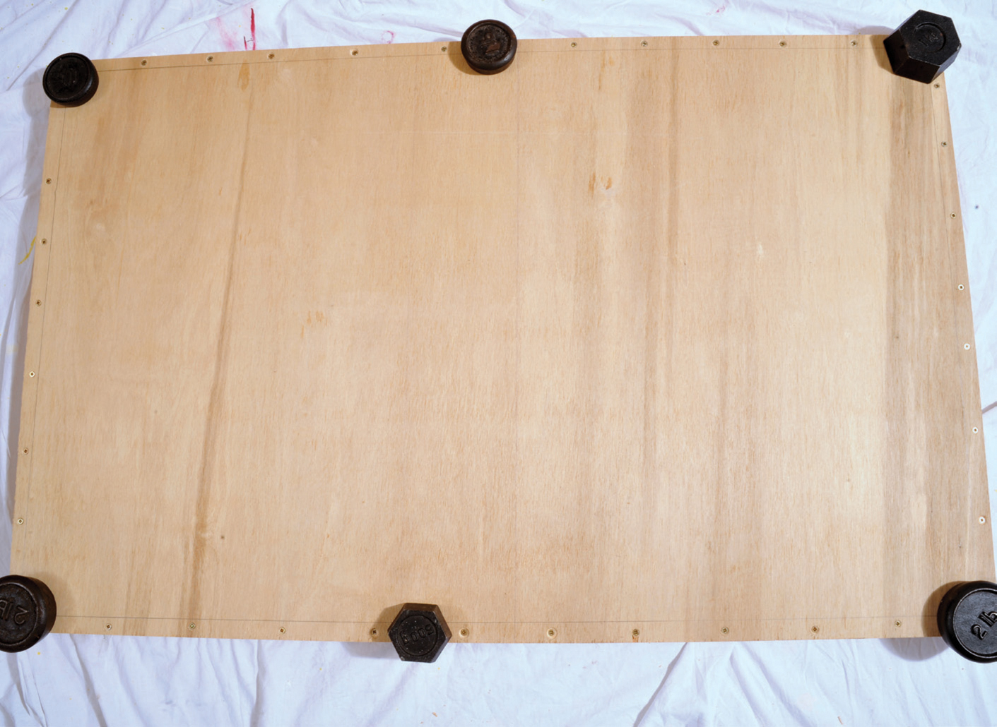
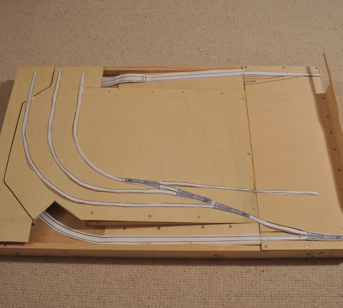
The almost complete flat baseboard constructed in softwood and plywood.
This chapter aims show you how to construct a variety of different baseboards, starting with the simple, solid wood baseboard and the standard door baseboard, followed by the real construction process of making your baseboard with a softwood frame and plywood board and other variations. It is heavily illustrated at each stage of construction, with a detailed explanation plus hints and tips throughout the construction process.
Previous chapters have already prepared all the ground and it is important that earlier planning steps have been followed. Before you start any construction you should have a full-sized drawing of the layout, so that you can accurately position cross-members and the spine. You should also be clear as to whether the board will have any rises or falls, as this could affect the depth of the frame.
The almost complete flat baseboard constructed in softwood and plywood.
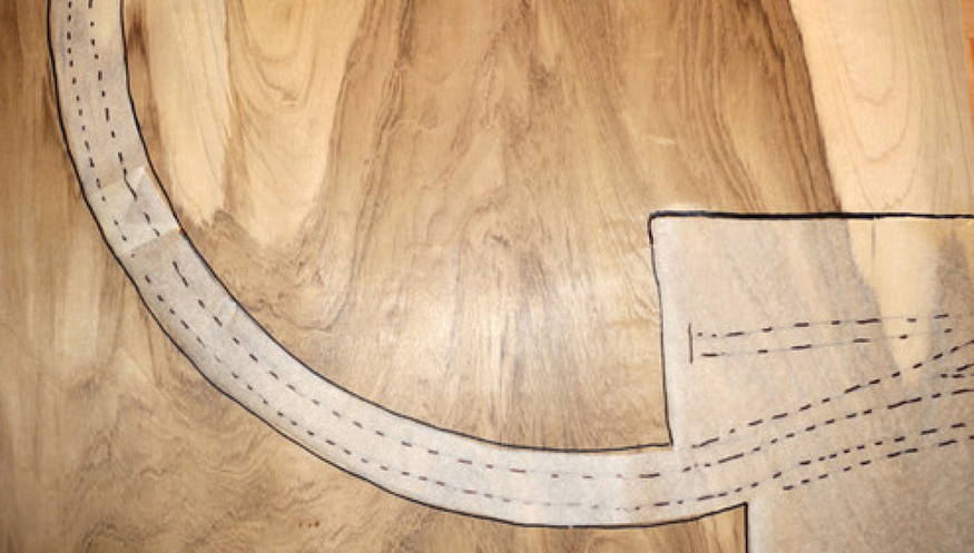
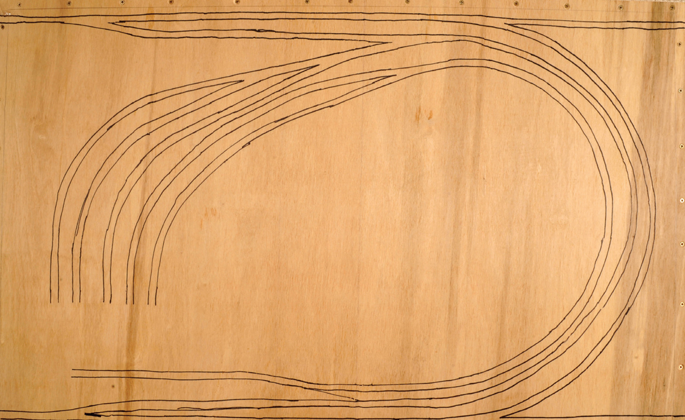
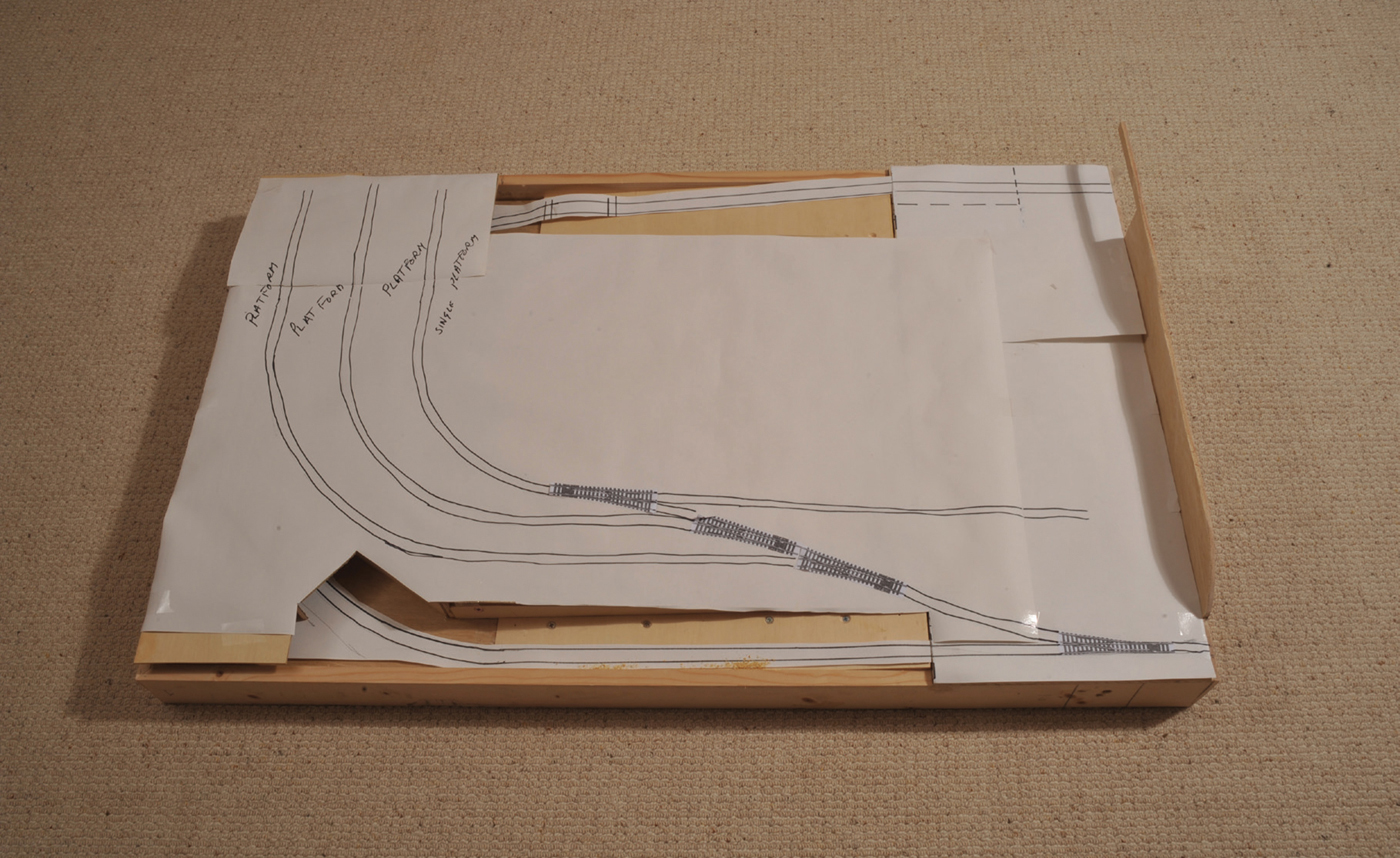
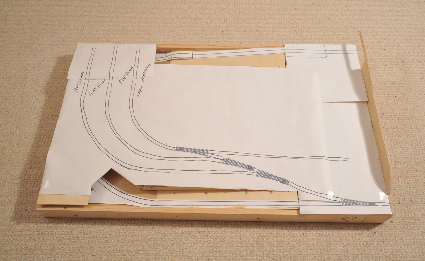
A full-sized plan of part of the planned track extension to ‘Pendleton Pit’. This board was covered in cork and the track plan was then laid on top so that excess cork could be removed. The cork was then stuck into place and, when dry, was painted black and then the whole board was sealed with a floor sealer to prevent water ingress. In the centre is a cork base, without paper cut out. This will accommodate the mine track, which is totally separate from the main layout. This paper plan will be removed but form the guide when laying track.
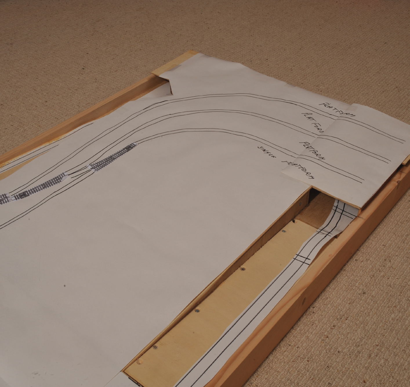
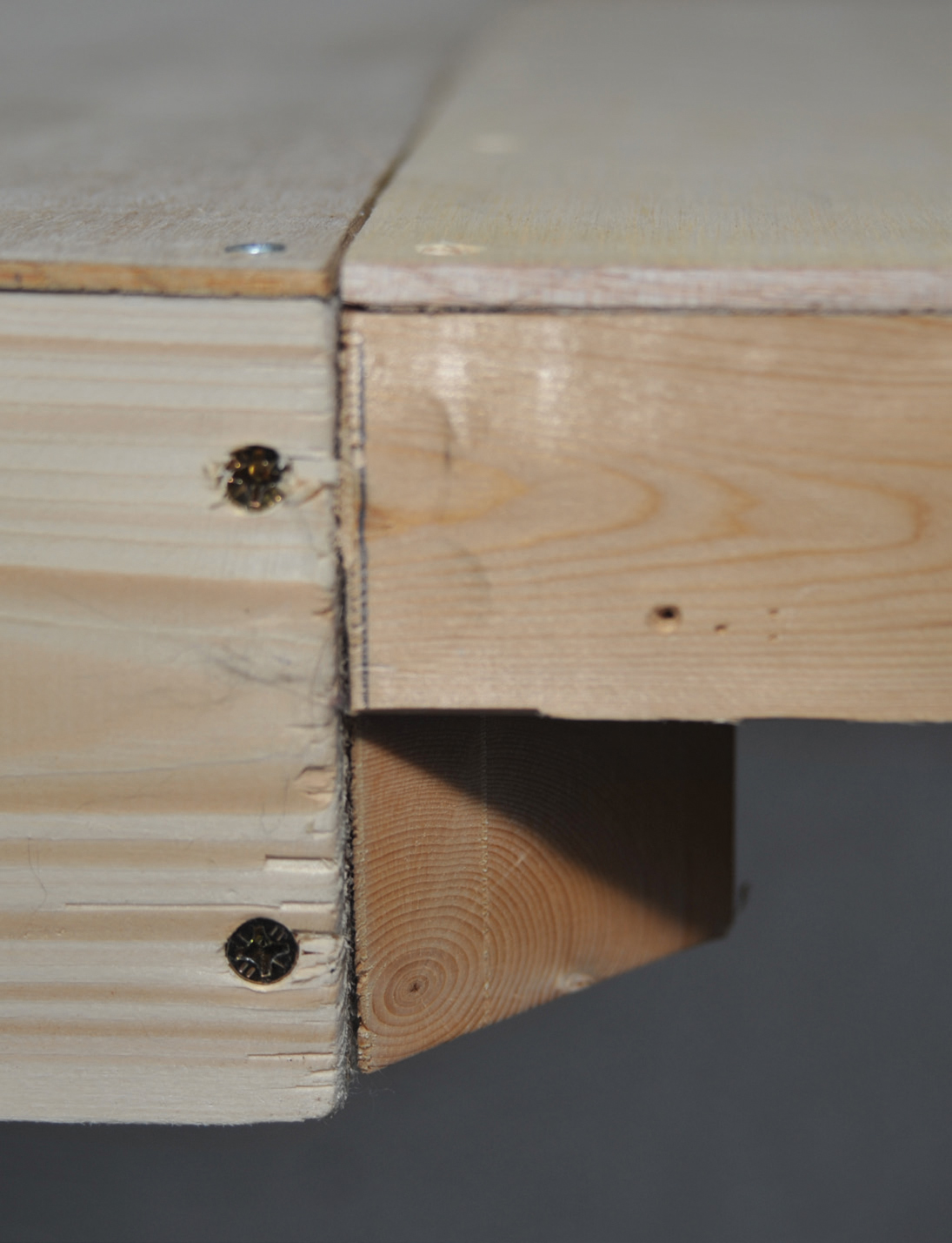
Plan and baseboard where one track passes under the other.
For the purposes of this book I am constructing several baseboards. The first board will be an extension to my existing two boards for ‘Pendleton Pit’ and will have a flat surface made to my standard size of 1,100mm (43in) by 700mm (27½in). The softwood frame will run around the edges of the baseboard, so it will be the full 1,100mm (43¼in) by 700mm (27½in). As it is level, it will be constructed in 18mm (¾in) by 44mm (1¾in) softwood, rather than the deeper frame required for the multi-height board.
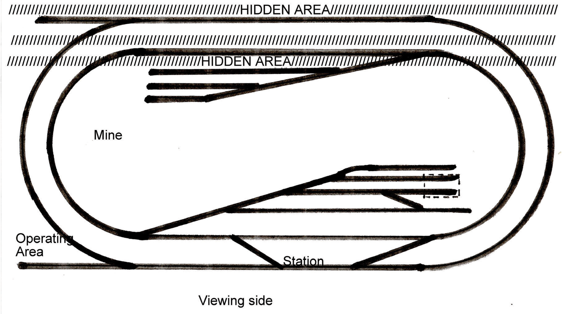
The first two boards of my current layout have completely flat top surfaces, with the only rise in the ground being at the rear to hide the return tracks of this continuous-run layout. There are two ways that I can tackle the new extension. There will be a single track running round the perimeter of the board to join up with track on the linking board. The first and easiest construction will be on a flat baseboard with all the track that I wish to hide being either behind tightly packed buildings or underneath land that rises, leaving the level track to pass underneath.
The second option is to drop the perimeter track gradually down to a lower level with the ground in the centre rising up slightly to create the height for the perimeter tracks to pass underneath. To achieve this in 1,100mm (43¼in), one track will have to fall as the other one rises. This obviously adds complications to the construction of the baseboard, but this chapter will show how this is achieved. The frame on both of the original boards is made up of 18mm (¾in) × 44mm (1¾in).
Solid wood boards are rarely used. They are heavy to store or move around, costly to make and have similar inflexibilities to the egg-shell door. Sheet timber is expensive and anyone wishing to use a solid board would be well advised to look in second-hand shops or auction houses for old dining-room tables to use as their baseboard. Such tables can be purchased for a song if they are not in good condition.
The only construction work for a solid wood baseboard is to cut it to the selected size and to consider how it is going to be supported. Size calculations are referred to throughout the book and you need to have given full consideration to weight, storage, track radius requirements and the board’s support before you cut the wood to the appropriate size. Before you lay the track you need to sand and finish the board as described in Chapter 9.
A solid wooden baseboard.
The egg-shell baseboard comes in one or two sizes, so you will have to reverse the considerations. Where can I store the layout? Is the layout too heavy? What diameter track layout can I fit on the board? These are all questions to be considered before you choose this option. As with the solid wooden baseboard, this door will need finishing before the track is laid, as described later.
Cheap doors are made with two layers of hard-board with cardboard innards and a thin, wooden frame. These doors used to be easily available, but today even the simplest door is made from a thin timber veneer. Such doors are about the same price as a 1,220mm (48in) × 2,440mm (96in) × 6mm (¼in) plywood sheet. Standard doors are 1,981mm (78in) high and between 760mm (30in) and 838mm (33in) wide. They are rigid and they are light. You cannot screw or pin track to the board – it all has to be glued and you cannot install point motors below the surface. Wiring and motors all have to be on the surface. Doors make an ideal baseboard for the simple home track where points are operated manually and there is a simple track layout, which can be brought out when children want to play with trains.
By far the simplest proper baseboard you can construct is the flat baseboard and I suggest that more complicated boards are not tackled until a flat one has been constructed successfully, as this is the basis for most of the other types of baseboard, whether multi-height baseboard, dropped baseboard, layered height baseboard or open-topped baseboard.
Plywood frames are usually constructed of 9mm (⅜in) plywood. The process is exactly the same as for softwood frames described above, except that as 9mm (⅜in) plywood is only half the thickness of 18mm (¾in) ×44mm (1¾in) softwood, all the measuring and drilling has to be that much more accurate. Corners, as with softwood, can either be mitred or edge-to-edge (butt) jointed. With plywood you are not restricted by standard depths, as you can cut it or have it cut to any depth you like. I would, however, strongly recommend that you have it professionally cut into strips. This leaves you with the simpler task of just cutting each piece to the appropriate length. There is little point in using plywood unless you need a depth greater than 50mm (2in), as the minimal weight-reduction between plywood and softwood at 44mm (l¾in) is offset by the increase in difficulty of screwing the top to the frame, due to both the narrower width and the plywood construction. Screwing into 9mm (⅜in) plywood requires each hole to be fully pre-drilled and a thin screw, otherwise plywood has a tendency to split away when screwing into the end grain. The biggest factor is the weight. Plywood is approximately 50 per cent of the weight of the thicker softwood. If weight is crucial and you are an accurate worker, then use plywood. However, if weight is crucial it is possible to use a spade drill to bore a series of holes in the softwood frame to reduce the weight, but the amount of weight saved compared with the work required could never be classed as beneficial.

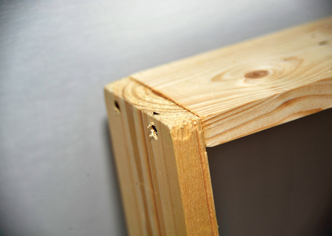
A commercial plywood frame corner joint. ELITE BASEBOARDS
As recommended earlier, I have drawn up detailed full-sized track plans for each board on to lining paper and I am clear that my track requirements will fit within that space, whilst not interfering with the frame itself. To make matters easier, I only have four points on the outer line of the flat baseboard plan and only two on the multi-height board plan. The baseboard must be designed around the track plan, not the other way round.
I strongly recommend that, if you are having the sheet plywood professionally cut to the required baseboard top size, you make up and glue the actual frame first. Only when this is complete, have the baseboard and the internal cross-members and the spine cut to the size of your frame. The reason for this is that a professionally cut board will be accurate to the millimetre and in making your frame you could easily be the odd millimetre adrift. On the other hand, if you are cutting the baseboard top yourself, I would cut this first and then cut and make up the frame. It is far easier to remake or trim a piece of frame than it is to make corrections to a baseboard sheet. It is always best to cut framing a thousandth of an inch oversize and trim back when it is found to be too big, when you hold the individual pieces in position. It is easier to trim back than it is to add to a length. Do not think about fixing the frame pieces together until you are certain that they exactly fit the baseboard sheet.
I cannot stress too strongly the adage ‘Measure Twice – Cut Once’.
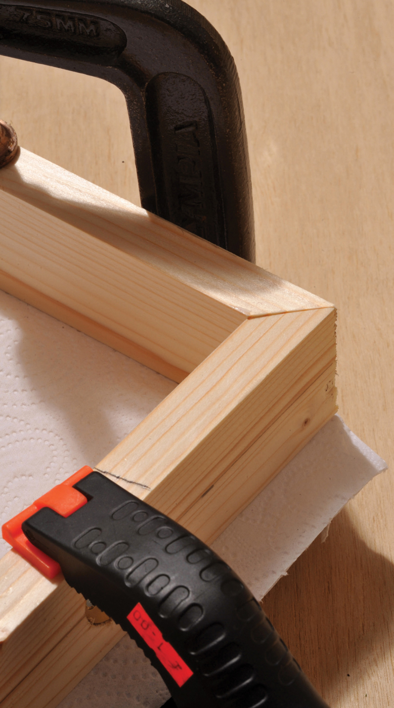
The frame can be joined at the corners in a variety of ways. My personal choice is to mitre and screw each corner. Using a mitre joint gives approximately 50 per cent more surface contact area than a straight end-to-end joint, and with the aid of a mitre cutting block, is easily achieved. When using a mitre block always use a clamp to hold the wood, as this prevents the wood from moving during the cutting process. Fingers are not usually strong enough to completely fix the wood throughout the cutting process. A mitre join has the advantage of almost automatically making the corners 90-degree square, whereas an end-to-end joint is slightly less reliable. End-to-end joints leave the grain exposed on one of the two pieces of wood and you can only screw into one side, with the point of the screw going into the end grain of the other. Mitre joints allow you to screw into the sides of either length of wood or one screw into each side. There is no point in trying to accurately measure out the mitre by hand. Any DIY store or hardware shop will sell a simple mitre block and the only other item is a tenon saw. Ensure the length of wood is longer than necessary, then place the wood in the mitre block, as shown, and cut the first mitre.
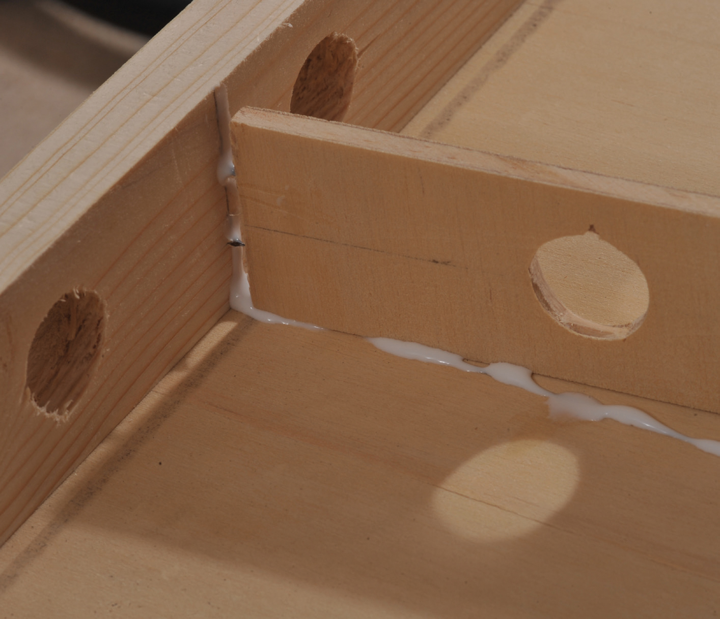
A butt joint glued and screwed. Note it can only be screwed in one direction.
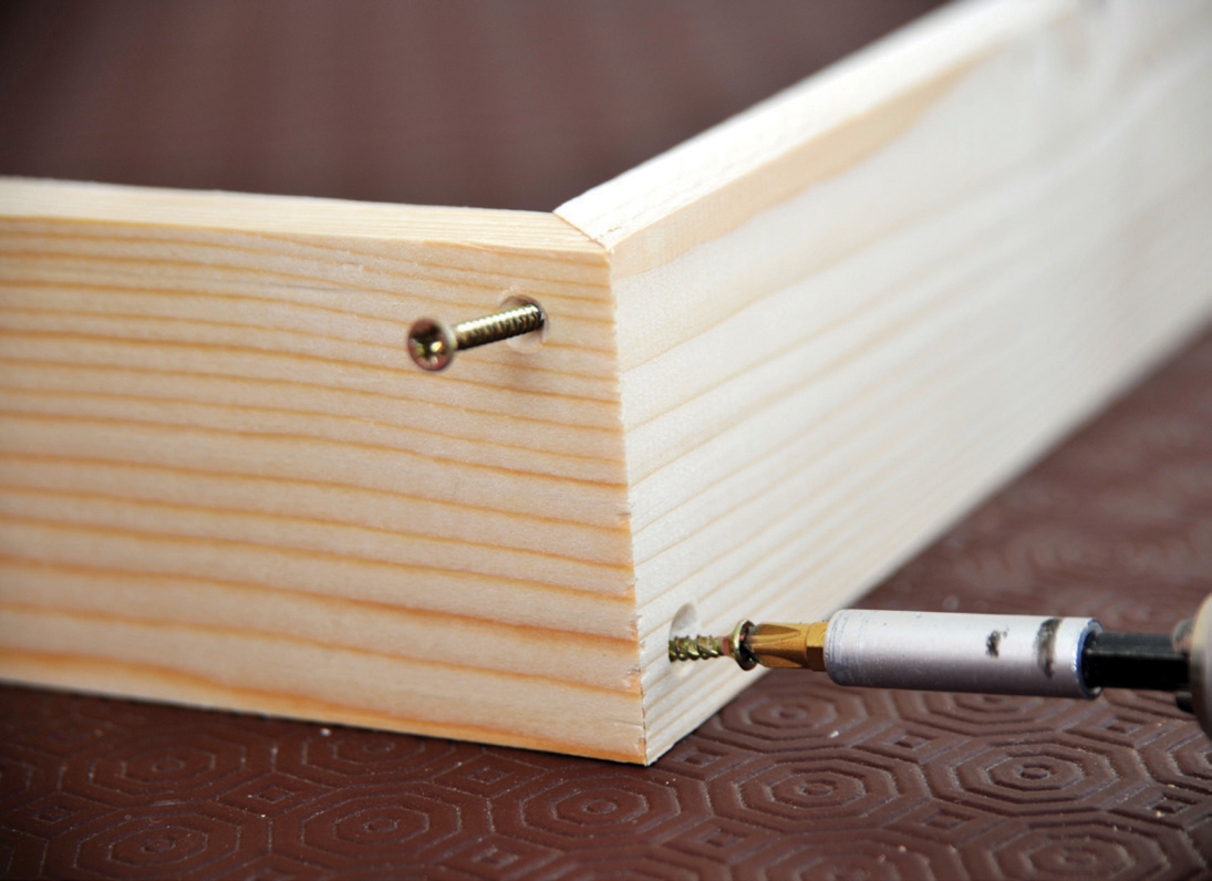
A mitre joint glued and screwed, with one screw from each side making a more rigid joint.
The next stage is to measure the wood from the mitre along the longest side, and mark carefully the actual length of the wood required. Check your measurements again before sawing and ensure that you have both mitre cuts facing towards each other, not parallel with each other. Make sure that the saw cut is slightly to the right of the distance mark, rather than sawing through the middle of the line, as you have to allow for the thickness of the saw blade. Always cut the longest sides first, as if there is a mistake they can always be cut down to form the shorter sides.
Double check the measurements before cutting the second length. Once complete, put these two sides well out of the way so that you are not tempted to use them for the shorter lengths. Now repeat the process with the two ends of the board so that you end up with the four pieces that form the frame. Push these all together on a flat surface and check that you have the right size of frame. If it is too long or too wide it is possible to shave thin strips off the offending lengths using the mitre block and tenon saw, but ensure that you take exactly equal amounts off each of the corresponding parallel pieces.
If you plan to use straight end-to-end butt joints, rather than mitres, still follow the instructions using the 90-degree cut on the mitre block, as opposed to the 45-degree cut. All the other instructions are the same.
Do not sand them down at this stage.
If you are making a layout that has more than one board, or you are adding to an existing layout, it is essential that you fix furniture maker’s joint dowels at this stage. Once you have the top of the baseboard fitted or, worse still, the cross-members and spine fitted, it is not possible to fit a normal drill and obtain an exactly parallel set of holes for the dowels. If you are making two or more boards, clamp each set of end boards together but ensure that they are in exact register and that the mitres are chamfered inwards, so that the two external faces of the frame are face-to-face. Put two pencil lines across the top but to one side. By matching these lines up you will ensure that you have the right pieces joining together and that they are both the right way up.
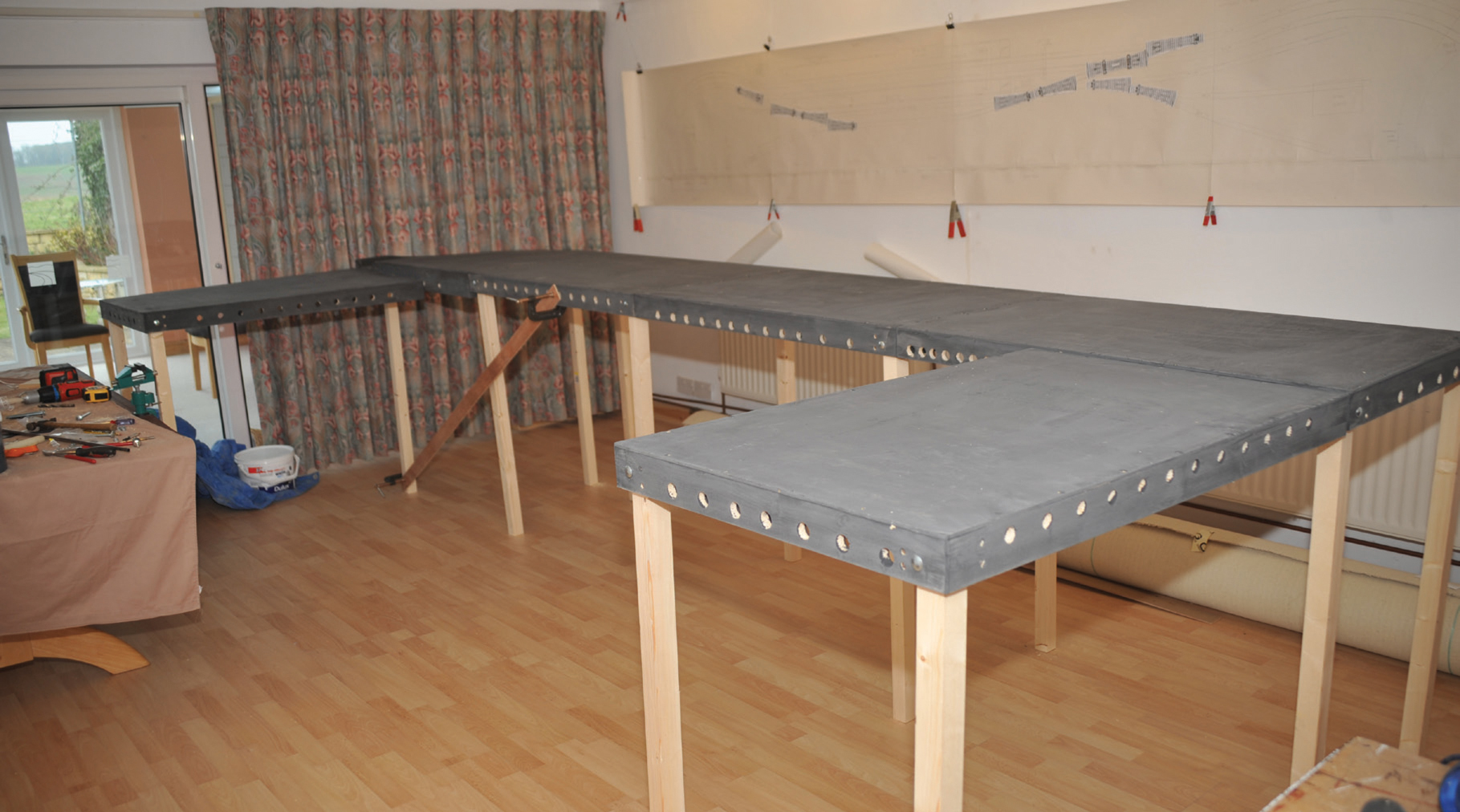
A multiple set of baseboards ready for track laying.
If you are joining a new board to an old layout you have to take greater care in ensuring that they are both accurately lined up. In my case, the end frames of the rise and fall baseboard are different depths to the baseboard fitted to the existing layout. You must double check several times that they are both clamped in exactly the correct position before drilling. Once drilled and the dowel installed there is no adjustment.
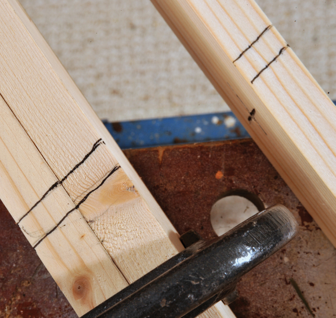
Lines marked on end boards to ensure a complete match between the two ends.

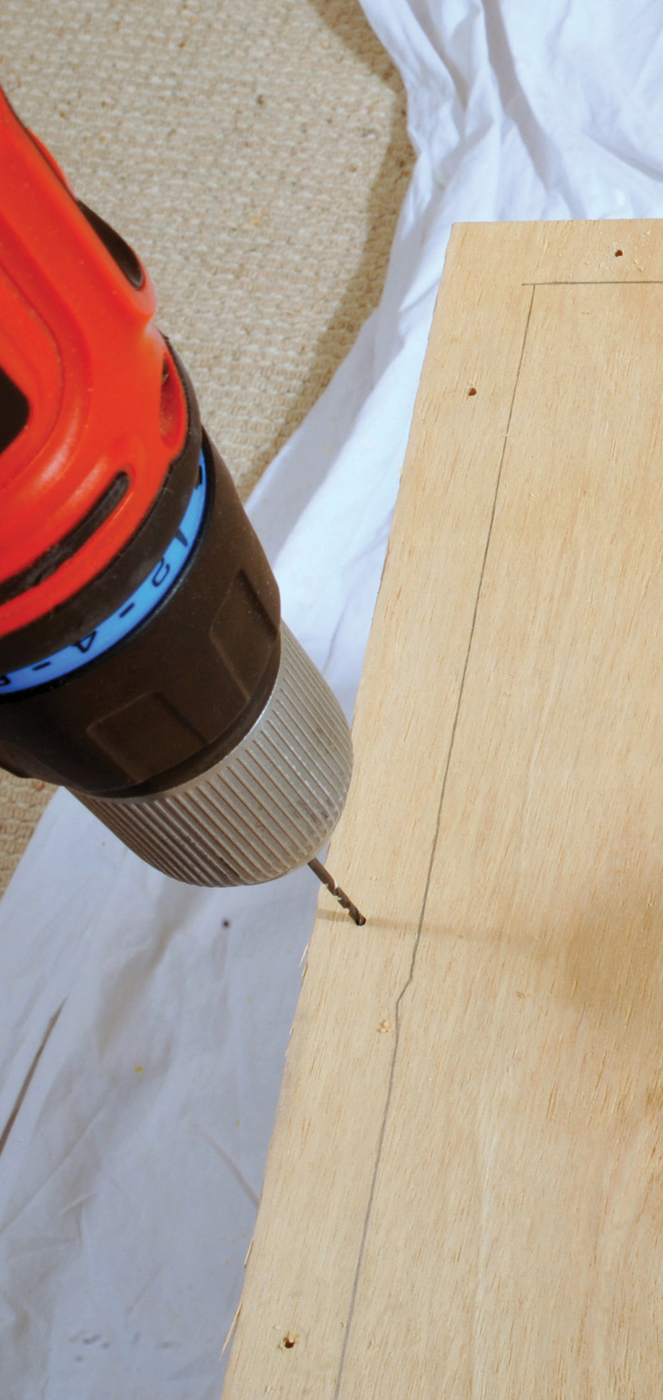
Drilling the pilot holes for dowels. Note the two pieces clamped together to ensure accuracy. An alternative is to use a simple jig.
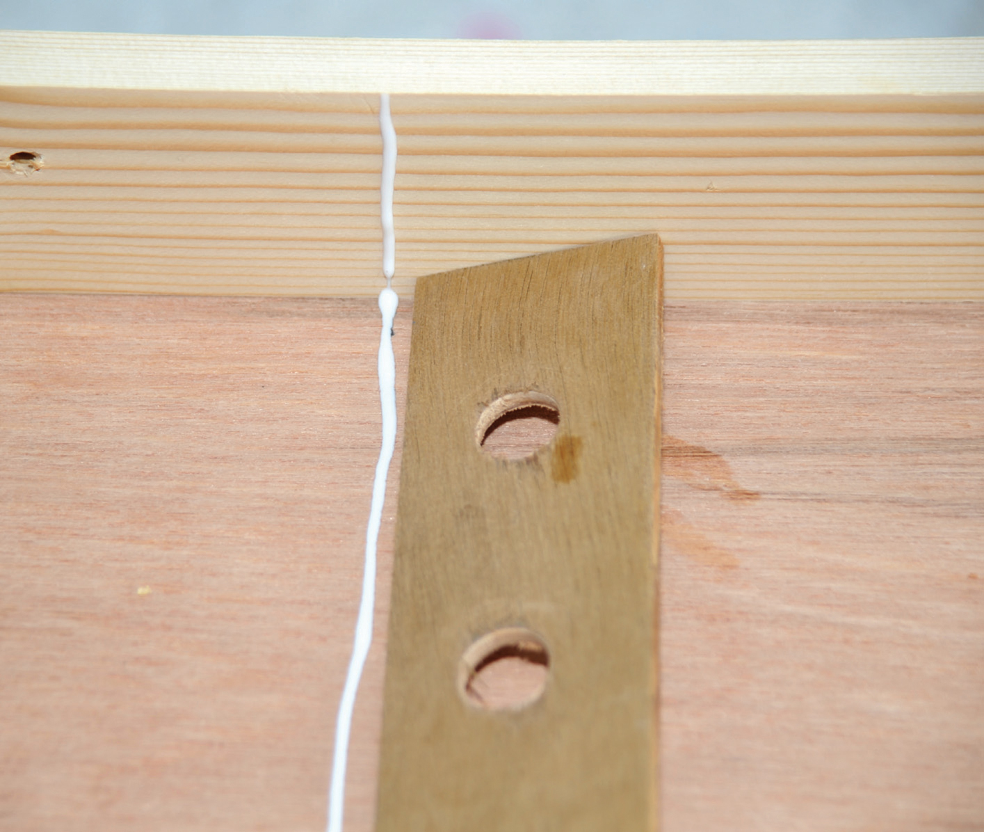
To install dowels, first drill a hole through both end panels with a 2mm (1/20in) (or similar sized) drill bit. The dowels need to be fitted about ⅙th of the way in from the sides to ensure that the boards marry up exactly across the whole width. If you are going to fasten the two boards together with bolts, you also need to drill two holes using a 10mm (3/10in) bit. These holes need to be about one third of the way in from the sides. There are other ways of joining boards that do not require drilling at this stage. The main alternative is the toggle latch (see Chapter 10).
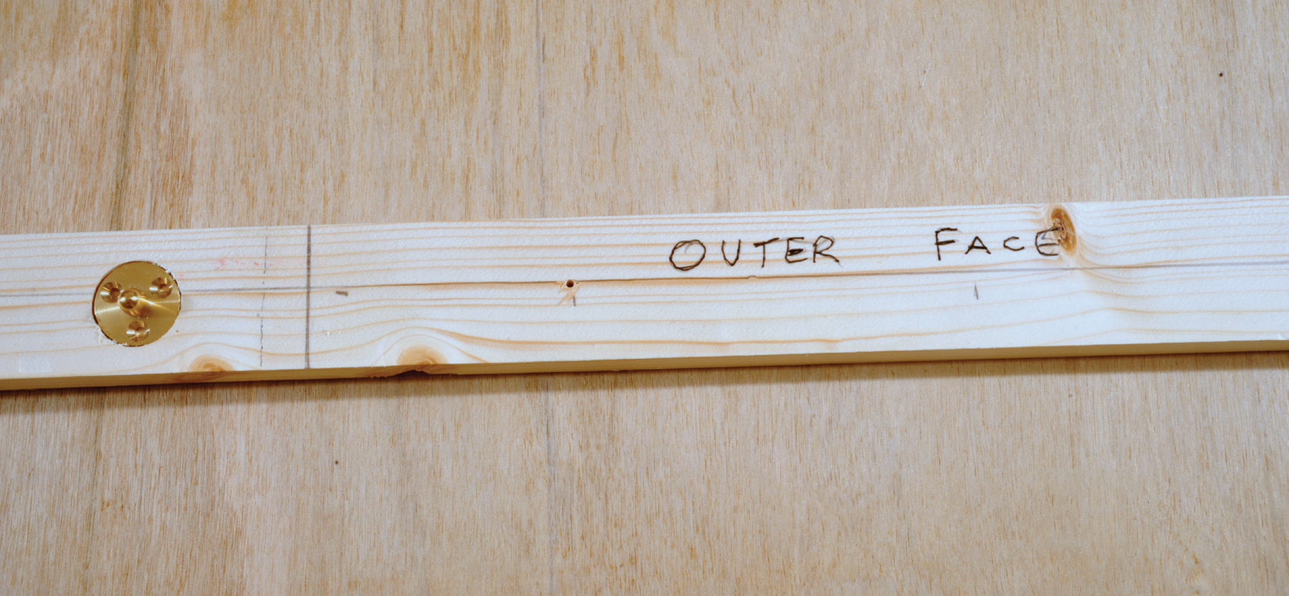
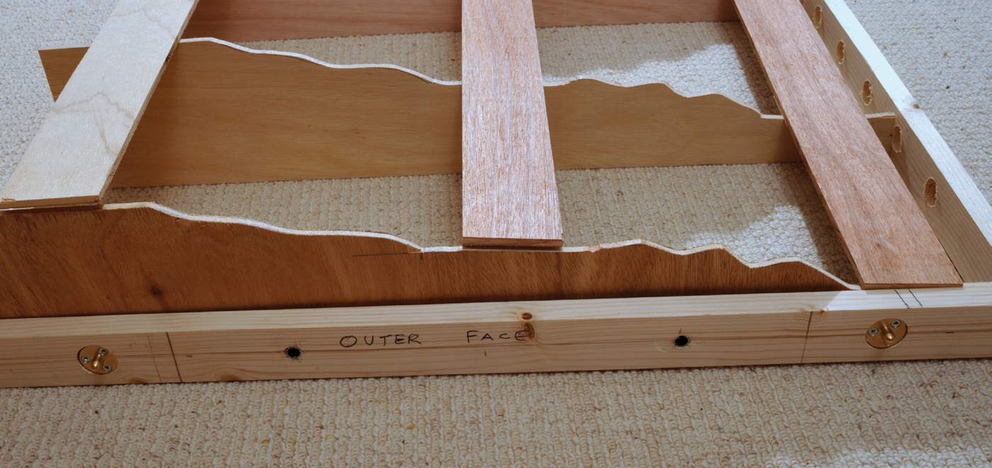
Once the pilot holes for the dowels have been drilled and other holes (if bolting the units together), you can undo the clamps and separate the two ends. Clearly mark the two faces that will come into contact with each other when complete. These boards will have an off-centre mark on the top and be clearly marked that they are the outer sides of the frame, and also a frame number if you are producing more than two boards. In this way there is little possibility of drilling the wrong side or in the wrong position.
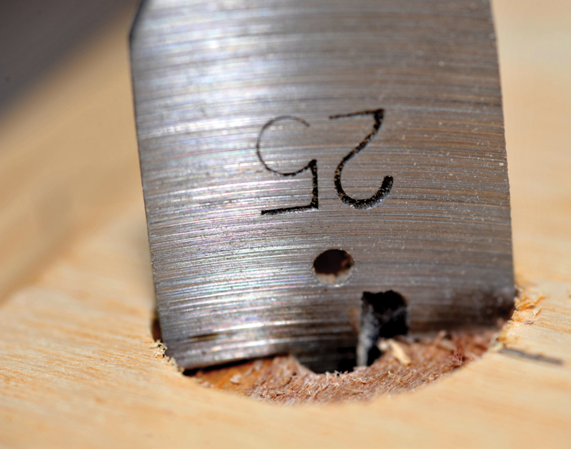
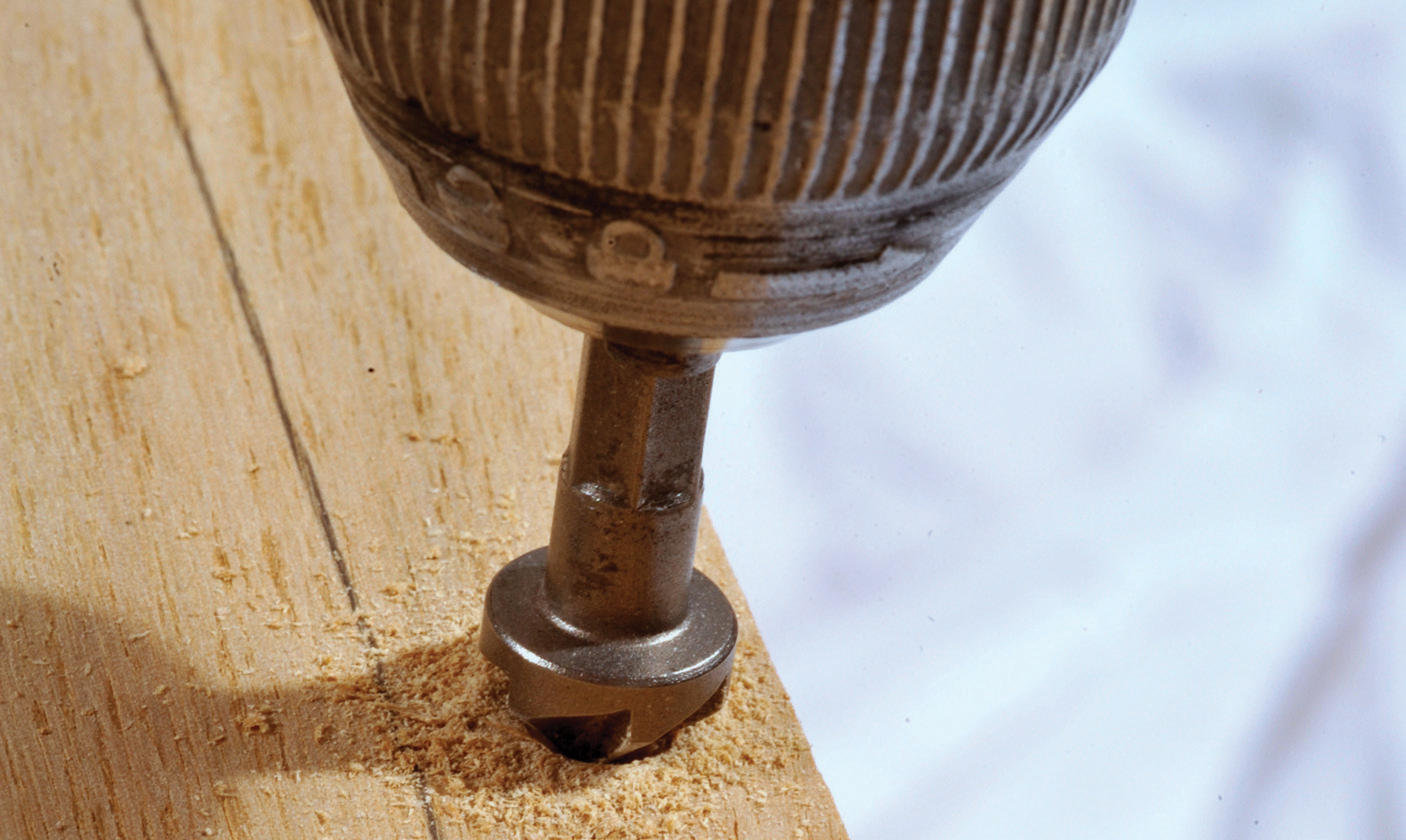
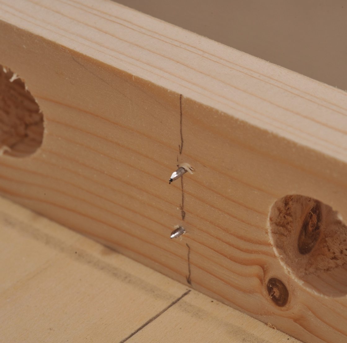
On the outer faces of each end use a flat (or spade) 25mm bit. You must keep the drill at 90 degrees to the wood and drill out just sufficient to fit the dowel plate into the wood, so that the front face is level with the surface of the wood. If you drill too deeply, the point of the dowel will not completely go home into the female end of the dowel. If you do not drill deeply enough, the two pieces of wood will be kept slightly proud of each other. One advantage of using plywood is that you can see whether you are drilling accurately, as you need to ensure that you are removing the different layers of wooden laminate evenly, as the wood will probably change either colour or texture with each layer. The spade drill is not totally flat and it cuts minimally deeper on the outside edge than in the centre. It is important that you drill just sufficient to leave the foot of the dowel minimally protruding from the surface of the wood. Then, using a 16mm spade drill, carefully remove the slightly higher centre, so that the dowel sits flat and level. (The remaining slight rise at the very centre will be levelled out when the screws are inserted and the wood compressed.)
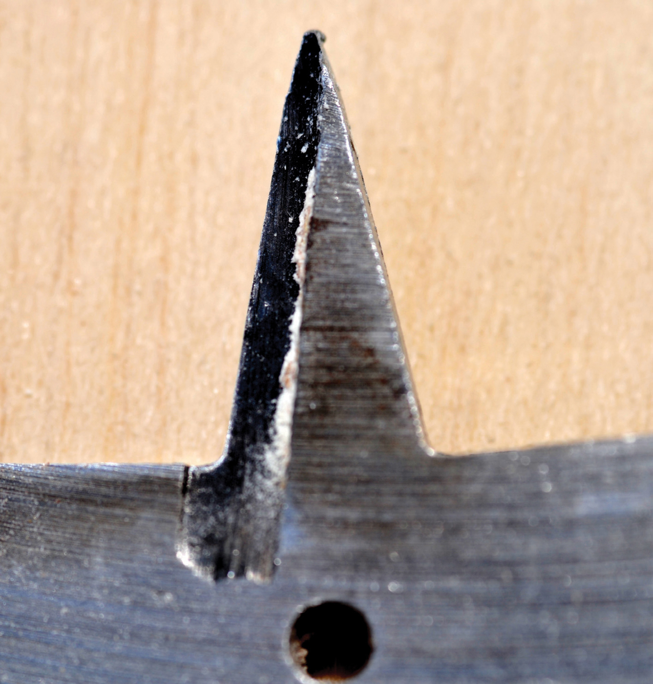
The point of a spade drill bit to be inserted into the pilot hole to ensure both ends are lined up correctly. Note that the ‘spade’ part of the drill bit is taller on the outside than in the centre. The hole it cuts out is therefore slightly humped.
A partly drilled hole for the dowel. Drilling stops just before the dowel is level with the wood surface.

A 16mm (⅝in) drill bit removes sufficient of the ‘hump’.
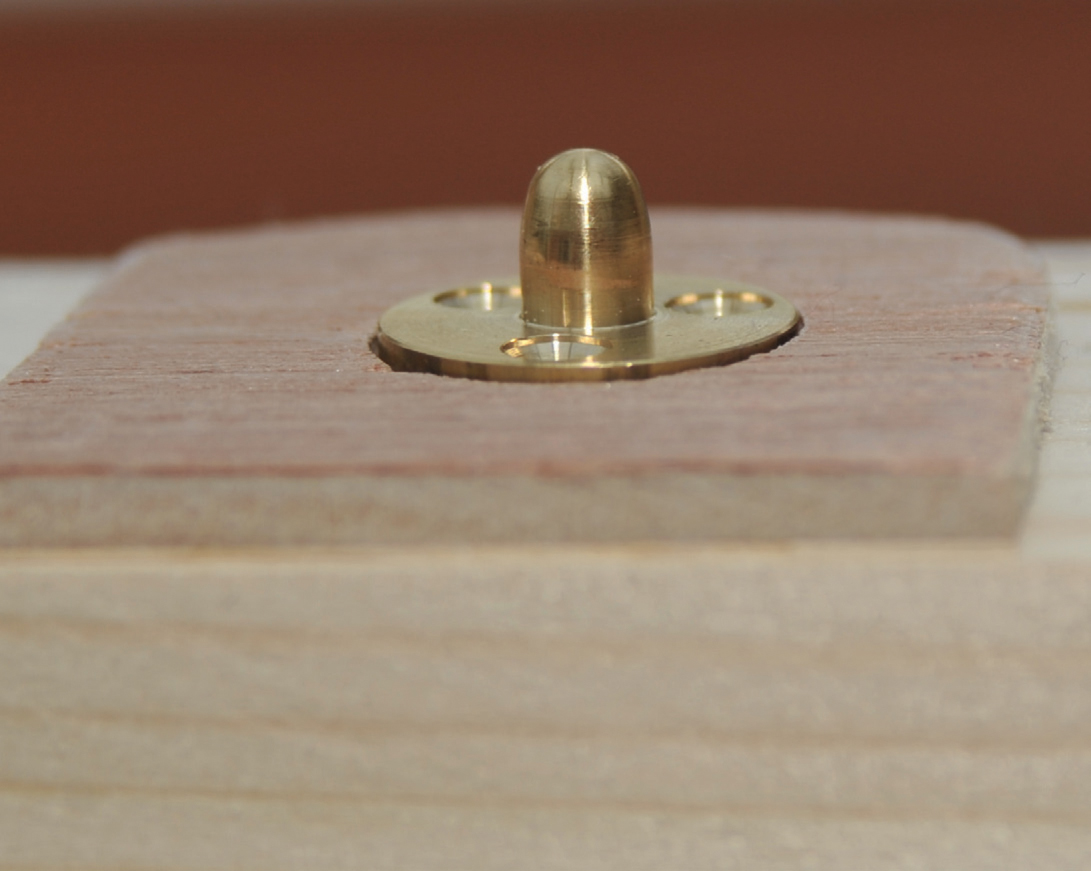
A dowel, slightly above the surface level and also rocking on the small ‘hump’ left by the 25mm (lin) drill bit.
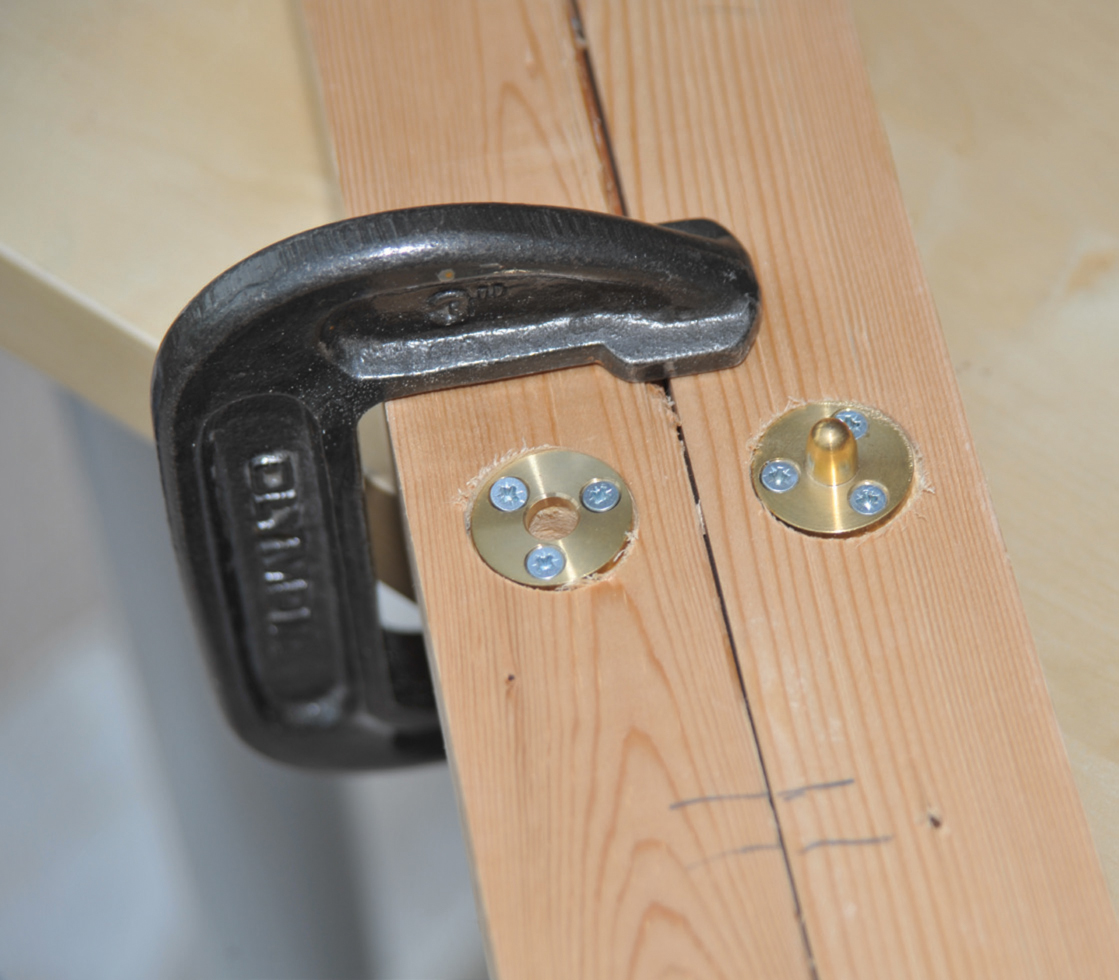
The hole you have drilled is 25mm (1in) diameter and the dowel is 24mm, so there is a little slack; however, the dowel needs to be in exactly the right place. Fix both the male dowels with only one of the three screws, and make sure they are tight. The wood behind the centre of the female dowel needs to be enlarged to accommodate the male dowel. Use an 8mm (⅝in) drill bit to bore this hole. The hole can go all the way through, or it can be just sufficient to take the depth of the male end of the dowel (approximately 12mm/½in deep). Then fit the screws to tightly hold the female ends of each dowel. Push the two wooden ends together and ensure that they line up exactly as you want, ensuring that the tops are level. Carefully ease the two wooden ends apart and, without moving them in their holes, screw up another screw on the male dowels. Once again clamp them together to ensure that they line up correctly, then carefully separate and screw up the remaining screws on the male dowels. If for some reason they do not exactly line up the two surfaces, you can adjust them by loosening one set of screws and turning the dowel to give you fresh wood to try again.
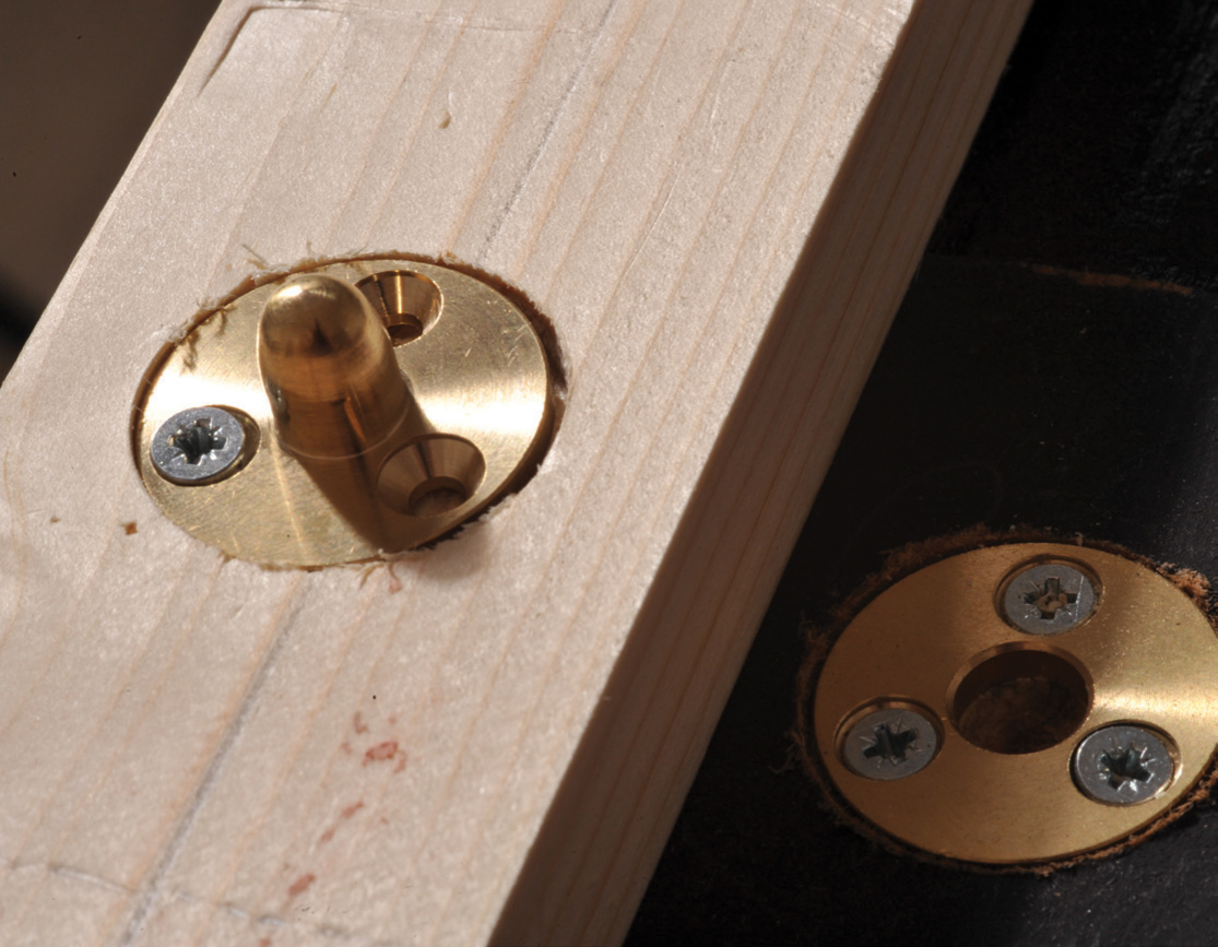
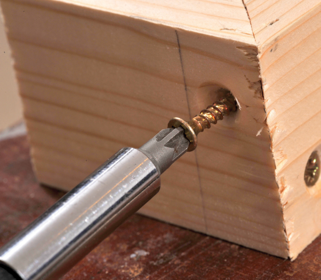
Male dowel with one of its three screws being tightened into place following verification of the correct alignment. The female dowel with three screws fixed.
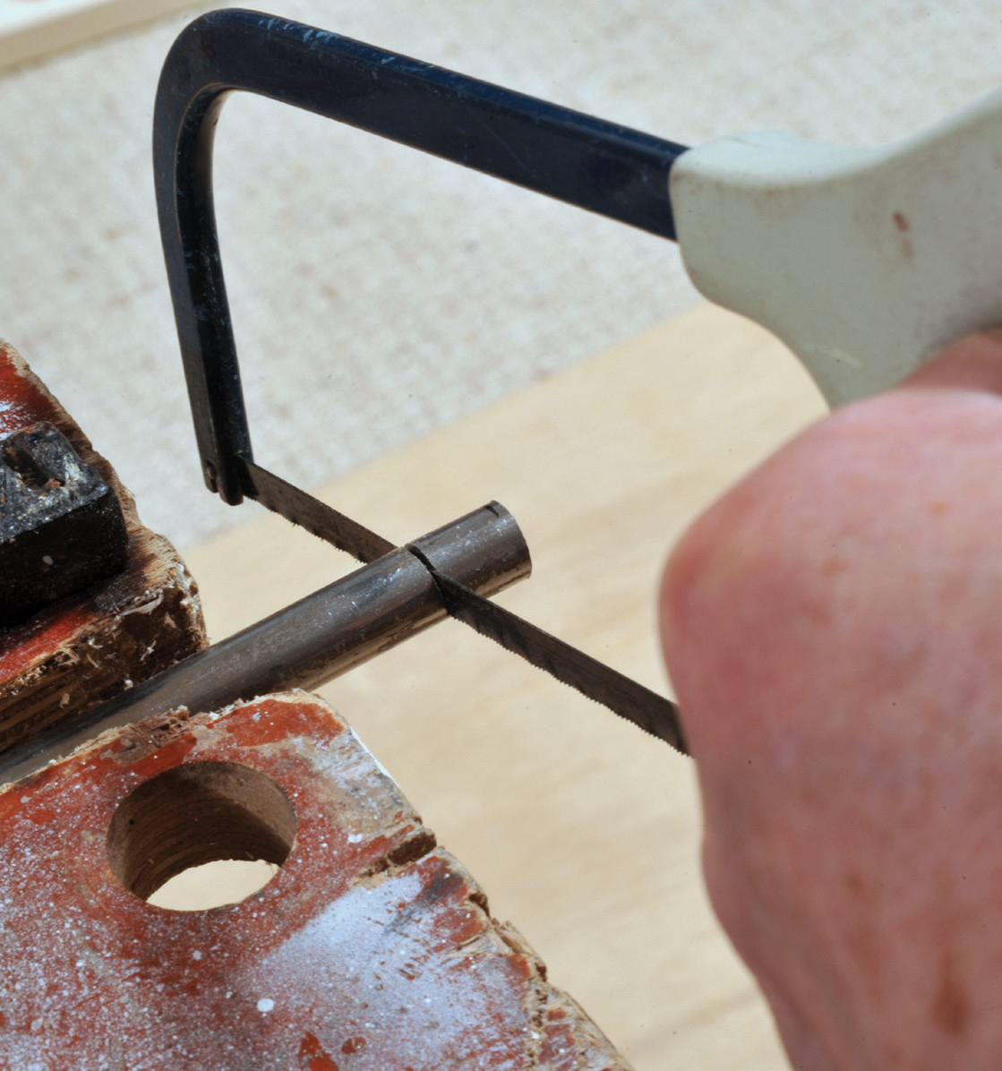
Cutting a length off the rod to fit in the end plate to ensure continued accuracy of the joining bolt.
If you are fitting bolts, you need to insert a metal rod in each piece of wood, otherwise, over time, the hole will become slack. The hole you have drilled will be just too tight for the rod, so it will have to be hammered home. Once again, clamp both pieces of end panel together with the dowels in place. Cut the 10mm (3/10in) rod into lengths slightly shorter than the width of the frame (in this case less than 18mm/¾in). Coat the wooden hole with UHU or a similar glue to bind the metal to the wood, then, resting the cut rod on the hole, insert an M8 bolt through the rod and both pieces of wood. Use the shaft of the bolt to guide the rod and the bolt head as the ‘punch’ to drive the rod home. Once complete, remove the bolt and repeat on the other face. This will ensure that both rods are installed correctly and that they line up with the bolt, at the same time as the dowels are correctly aligning the ends.

Installing the rod in the second end plate by passing the bolt through the end plate with its rod in place and knocking the new piece of rod using the bolt as a guide.
If you are fitting a different jointing system, such as toggle clamps (a preferred option), this latter paragraph does not apply.
You can now unclamp the two ends and ensure that you keep them as a pair.
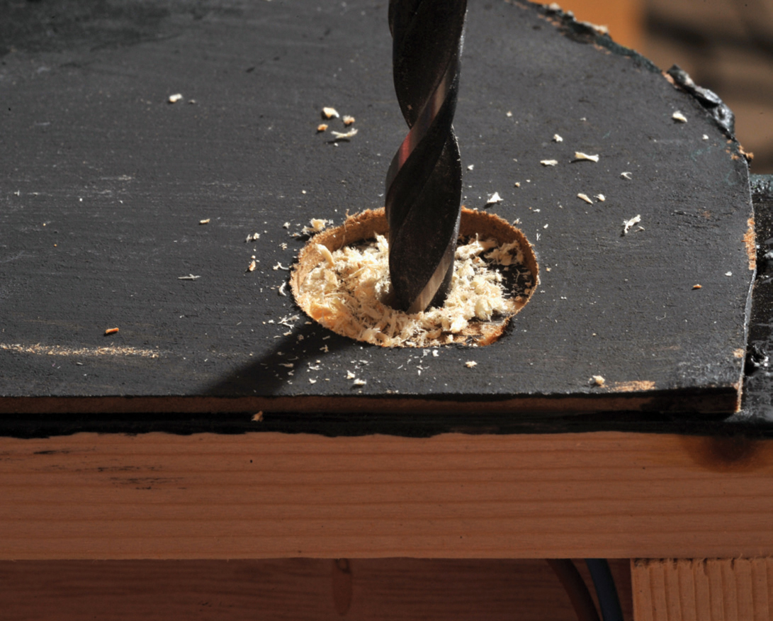
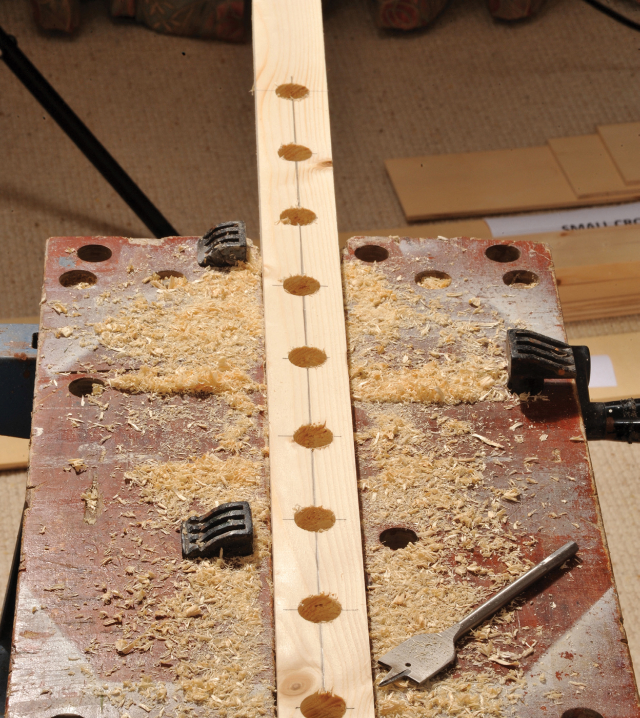
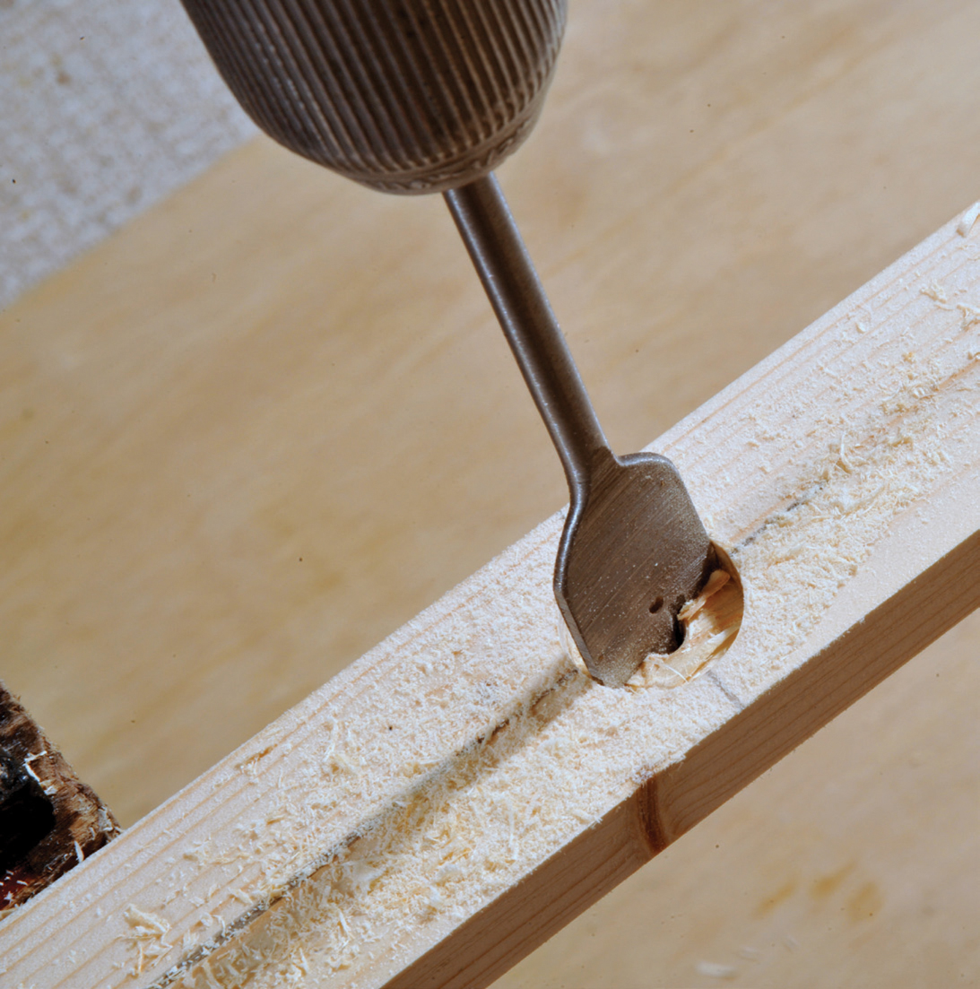
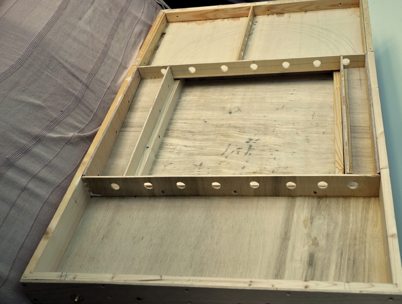
If you want to keep the weight of the baseboard to an absolute minimum, now is the time to bore a series of holes along each side and a couple in each end. (See note earlier in this chapter on the effort-for-gain benefits.) Carefully mark out the centre line of the wood and then mark out a series of equally spaced points about 75mm (3in) apart. Leave 150mm (6in) at each end to allow for the fitting of the leg supports. Using a 25mm (1in) flat or spade bit, bore a hole until the point of the drill appears on the other side. Turn the wood over and drill through the rest of the way until the wooden ‘plug’ is removed. (If you only drill from one side, the drill will split pieces of wood on the reverse side as it makes its way though.) It is important to stop drilling and turn over fairly soon after the bit’s pilot hole has come through to the far side. The deeper you drill, the wider the pilot hole becomes and the less accurate will be the final, completed hole. I always leave the public (or viewing) side without holes to permit the attachment of a curtain with a Velcro strip. An alternative, especially when drilling plywood, is to clamp a waste piece of wood to the rear of the main piece and drill all the way through. In most cases this will prevent the rear of the main piece of wood from splintering.
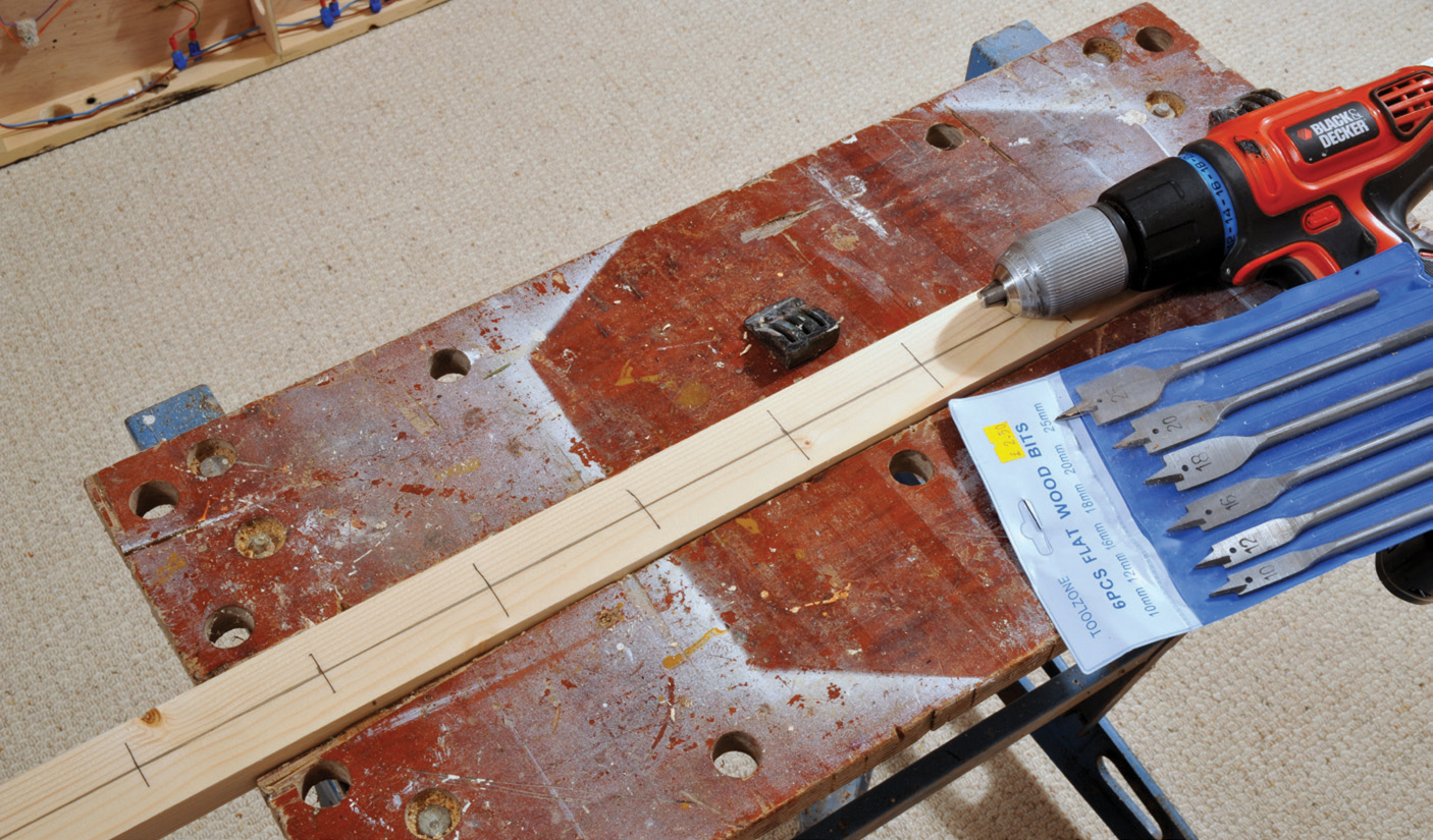
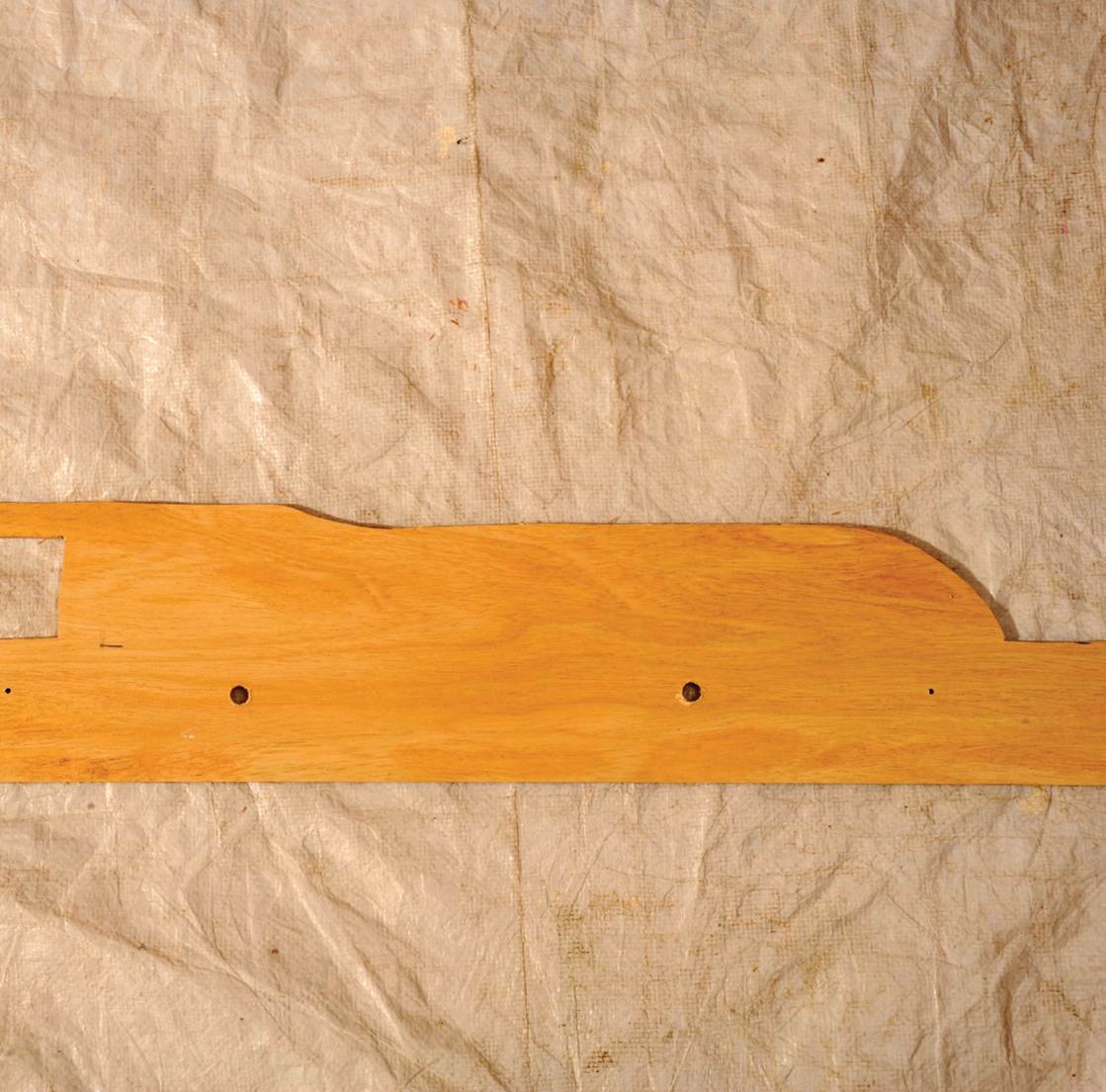
A side frame marked out ready for drilling in order to reduce weight.

Drilling out the side frame.
Two plywood cross-members with their backing sheet. Note that only the backing sheet of plywood has splinter damage.
The next task is to make up the frame. If you have mitred the joints, you need to clamp them together and ensure that they are flat. The best way is to have a sheet of wood that you know is square, place a piece of paper over one corner and then align the first side so that it is exactly in line with the side and comes exactly to the corner. Using at least one clamp, fasten the side to the piece of wood. Taking the other side, drill a couple of pilot holes ready for screws and use the countersink bit to ensure that the screws will fit flush. Smear glue on both mitres and bring the two pieces together. Clamp them both in position, but have one clamp extremely tight and the other clamp permitting slight movement. The piece with movement must be the piece with the screws. Check alignment with a set square. Tighten up both screws and then tighten the clamp. Ideally, leave for a while for the PVA glue to set or at least begin to harden.
Undo the clamps and peel off the paper. The paper stops the glue making a bond with the sheet of wood. Repeat the process with the other two sides to create the opposite corner. Again, using the wood as a template, join the four sides together. This should result in your completed frame, which is not only rectangular with 90-degree corners, but it will lay flat when put on a flat surface. Do not worry at this stage if it is slightly out of square as this can be corrected.
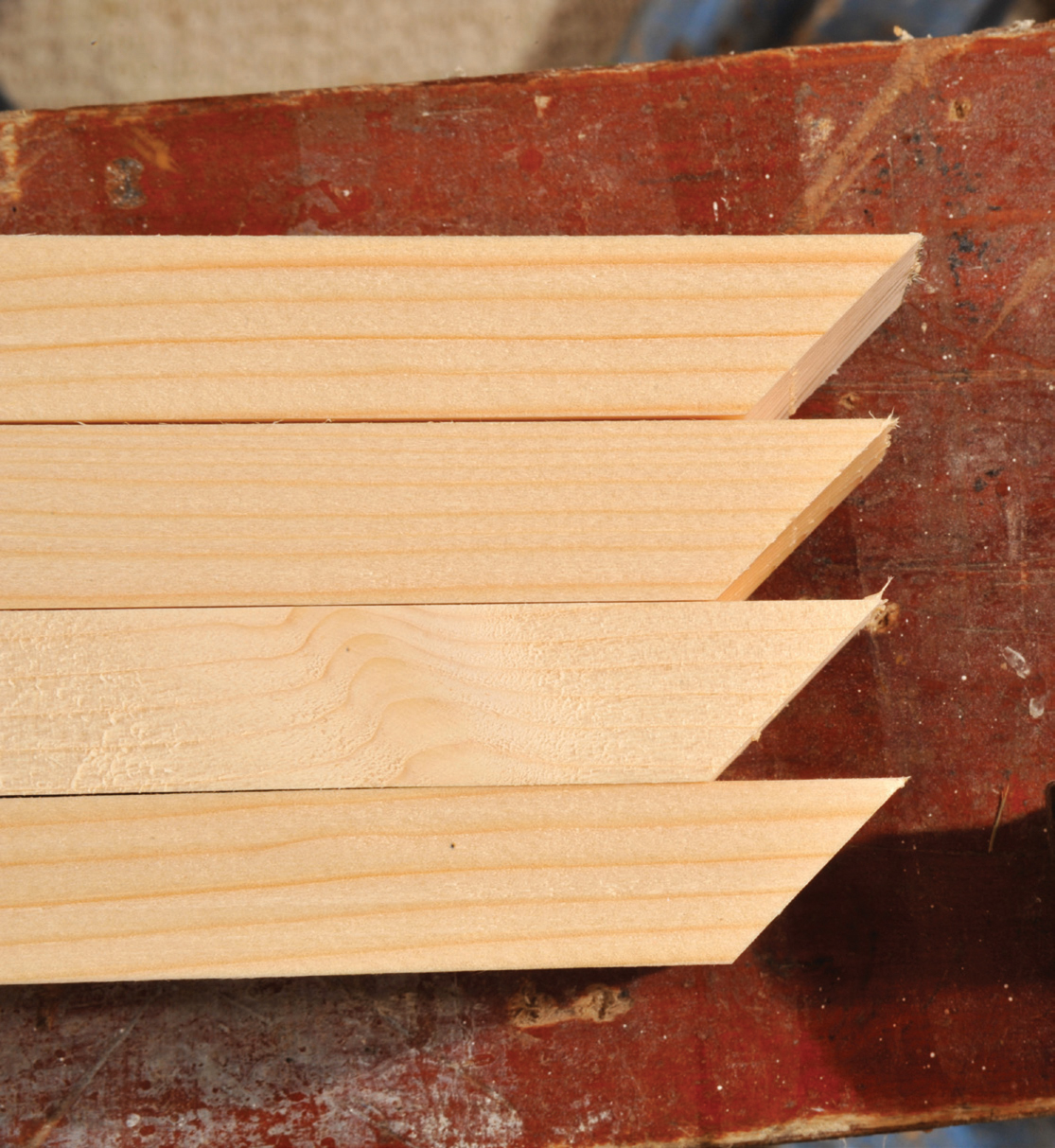
Two mitred sides and two mitred ends.
One side firmly clamped on to paper covered plywood with a guaranteed 90-degree corner. The end is clamped in place.
The end is screwed up tight and then clamped until dry.
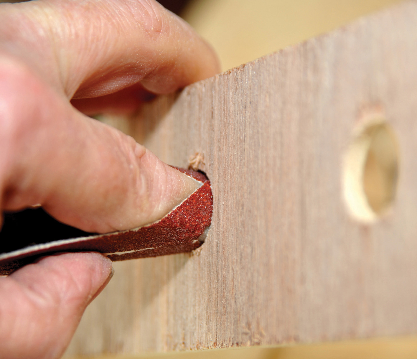
Leave the frame on a flat surface to hard dry, then sand down all the surfaces and the corners, either with a hand sander or a detail or plate sander. The holes along the sides of the frame are best sanded with sandpaper wrapped round a finger.
Instead of using a tenon saw and a mitre board, you could use a chop saw. These saws are very accurate and will cut an excellent mitre. Before you cut, make sure the saw is set to 45 degrees and that, if it is a compound chop saw, the blade is also set in the vertical position. Usually if you pick compound saws up to put them on a workbench, the blade will move slightly out of vertical because the grab handle is not exactly at the centre of balance. A compound chop saw will cut at any angle in both directions – vertically and horizontally – and it is vital in constructing a frame that the saw blade is vertical to the base and the other is 45 degrees to the cutting surface. Remember to allow for the thickness of the saw cut when positioning the saw blade.
The above frame construction processes apply to a flat-topped baseboard, a multi-level baseboard or an open baseboard, a dropped baseboard or a folding baseboard.
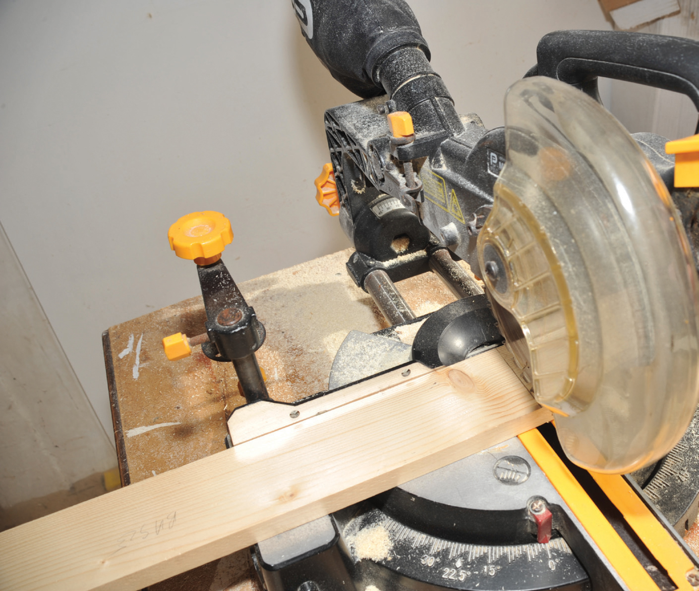
A chop saw cutting a 90-degree section of frame side. This saw can easily be set to cut mitre joints.
There are several materials used for baseboard tops. Historically, most modellers used to use Sundela board. Its advantages are that track pins can be easily tapped into the board and it absorbs noise better than other materials. The disadvantages are that in changing temperature and humidity situations it has a tendency to warp. It is also relatively heavy and the ends need to have some protection, otherwise corners and edges can easily break away.
In a few cases MDF has taken over as a preferred material. It is cheaper than Sundela and also cheaper than plywood, but it has the disadvantages that it too will warp under different humidity and temperature conditions, it is quite heavy and track pins need to have the MDF drilled, as you cannot easily knock them in. It also creates an appalling amount of dust when it is cut.
Common practice today is to use 3.6mm (1/16in) or 6mm (¼in) exterior quality plywood (slightly thicker if you are dealing with ‘O’ gauge). This has the advantage that it is light, almost waterproof and, when fixed with cross-members, does not warp. Its one big disadvantage is that it is noisy – it will ‘drum’ as trains pass over it. This is usually overcome to some extent by laying the track on a cork sheet. It also requires holes to be drilled for track pins.
There is nothing to stop you building the baseboard of much thicker materials but there is almost no gain in required strength. Making everything thicker results in the board being more cumbersome to move around and there is a tremendous increase in weight.
Plywood of 3.6mm (1/16in) thick only comes in widths of 606mm (24in) or less, but 6mm (¼in) plywood comes in a variety of sizes from 606mm (24in) × 1,220mm (48in), 607mm (24in) × 1,829mm (72in) and 1,220mm (48in) × 2,440 (96in). It also comes in 9mm (¾in), 12mm (‘in) and 18mm (3in) thicknesses. The size you require will depend on the size of your layout. If you are planning an end-to-end layout, you will probably not need a top wider than 606mm (24in), but as mine is a continuous layout I need it to be 700mm (27½in) wide. My only choice is the 1,220mm (48in) × 2,440 (96in) sheet. Whilst smaller sizes will fit in most cars, such a sheet obviously will not. I have a B&Q store not too far away that offers a cutting service and I would recommend anyone to make use of any company offering such a facility. Most places will make several cuts for free, but check before you commit. Not only do you get the wood cut square, without many chips being broken off by the saw, but you end up with it being easily transportable in a car and exactly the right size to fit your frame (if you have measured correctly).
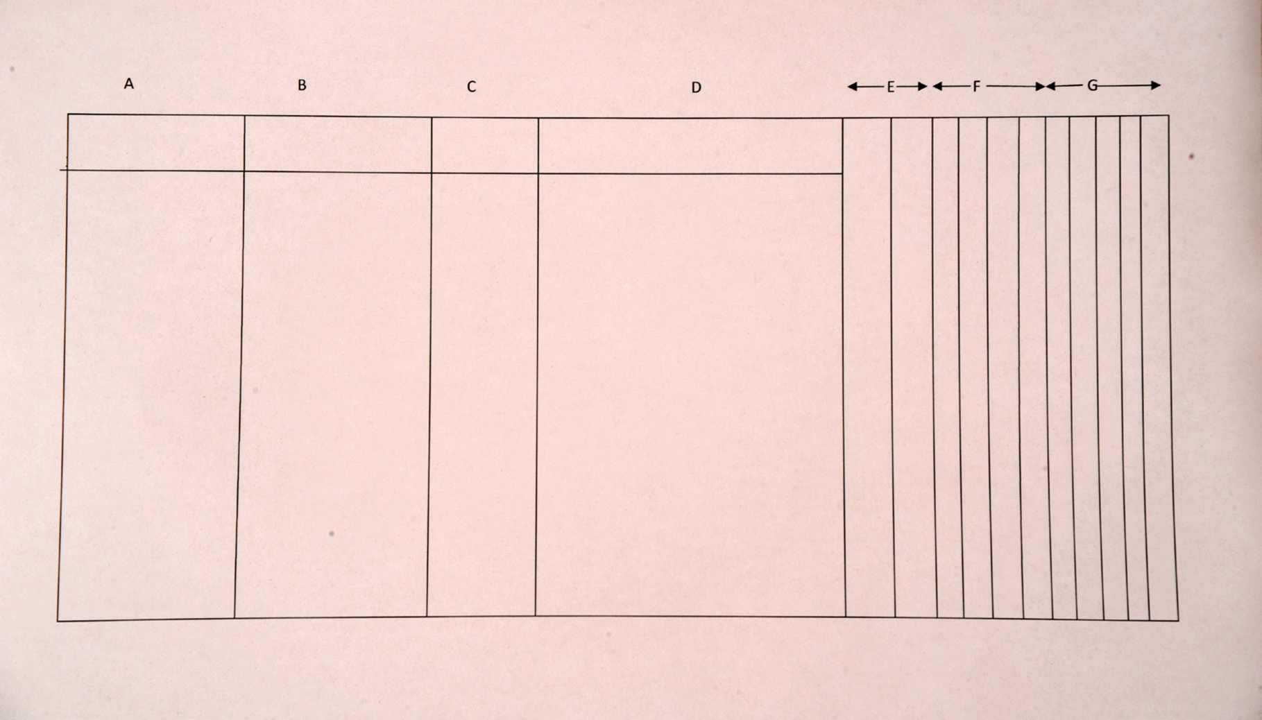
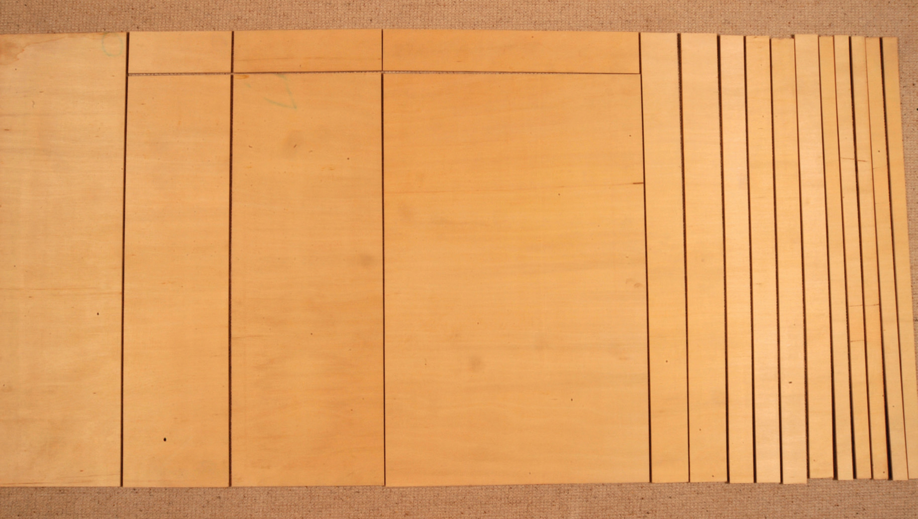
A cutting plan prior to having the plywood sheet cut professionally by B&Q. The letters indicate the cutting sequence.
It is not just a matter of working out the sizes of plywood that you want, but working out the best way of achieving this from the smallest piece of wood and then sorting out a cutting sequence. The big commercial saw machines stand the wood on its side and then cut vertically for best results. They usually cut from the right-hand side and it is possible to obtain thin slices of plywood for the cross-members and spine, if you have these cut whilst there is still a reasonable amount of remaining wood for the wood clamp attached to the saw to grip. Remember that the blade will take about 2mm (1/20in) from the wood, so you need to allow for this by leaving the piece resulting from this last cut a little flexible in its size.
The plan I have drawn up for my cutting requirements covers both the flat baseboard and most of the materials for the multi-level baseboard, as this will be the best use for a stock size of 6mm plywood sheet. The first five cuts will be 40mm (1½in) wide each. These will form the cross-members and spine. The next four will be 65mm (2½in) (the cross-members and spine for the deeper board). I will make the short cuts for the required lengths at home with a chop saw. The two pieces, each 200mm (8in), will form the up and down gradients. Next is the flat baseboard, 1,100mm (43in) by 700mm (27½in). The two pieces, 1,100mm (43in) by 280mm (11in) and 1,100mm (43in) by 400mm (15¾in), will form two of the different levels on the variable-height board. This single sheet of 2,440mm by 1,220mm by 6mm plywood will provide me with all I need to make up the first baseboard, plus the bulk of a second baseboard. As this baseboard will form part of an exhibition layout, the remaining sheet, measuring just less than 400mm (15¾in) by 1,100mm (43in), will be used to form a front slope that will carry printed information about the layout and the West Wiltshire Model Railway Circle, at the same time as keeping small hands away from the tracks and rolling stock. This unit just bolts on to the main baseboard when at the exhibition.
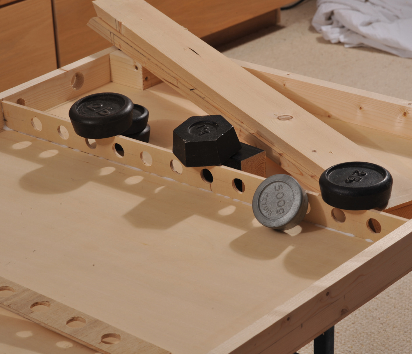
As soon as you get your cut plywood home, lay it flat on the floor so that it does not twist. It will have been in a wood store or warehouse, where both temperature and humidity are different than in a house or garage. To ensure it does not twist, also place some weights on top of the flat sheets – paint cans are ideal. Leave the sheets for a few days to acclimatize to their new conditions before starting work on them.
When you are ready, take a sheet and marry it up to the frame you have made and check that it fits. As long as it is the correct size, even if the frame is not completely rectangular, you can proceed to the next stage. Bore a series of 2mm (1/20in) or smaller pilot holes around the top edge of the baseboard sheet, about 75mm (3in) apart, and then use a countersink bit to countersink each hole. Before you apply PVA glue, ensure that you have enough screws to complete the task, as the baseboard top needs to be completely secured before the glue dries.
Lay the frame on a solid, flat surface and spread PVA glue on the top edge. Carefully locate the plywood baseboard on the top of the frame, adjusting it slightly until it is flush on one side and the two ends align correctly at the bottom corners. Do not worry if the top corners are not 100 per cent correctly aligned at this stage.
Screw home one screw in each of the two bottom corners and, if the softwood frame is slightly bowed, you can pull it in line before inserting the centre screw. As soon as it is flush, either hold it or clamp it in position and insert a screw in the centre. Now is the time to ease the frame into its final shape to fit exactly with the baseboard in all four corners. With one side fixed with three screws, push the frame into shape to match the baseboard top. As soon as you have it square, insert three more screws on the opposite side and then gradually go round inserting alternate screws. Finally, continue filling in with the remaining screws. This will pull the baseboard evenly in contact with the frame.
Boring pilot holes in the baseboard top prior to fitting.
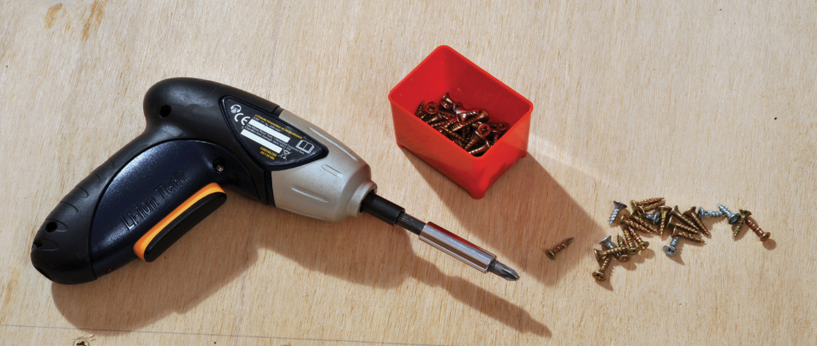
Ensure you have a screwdriver (with the battery fully charged) and the screws prior to gluing.
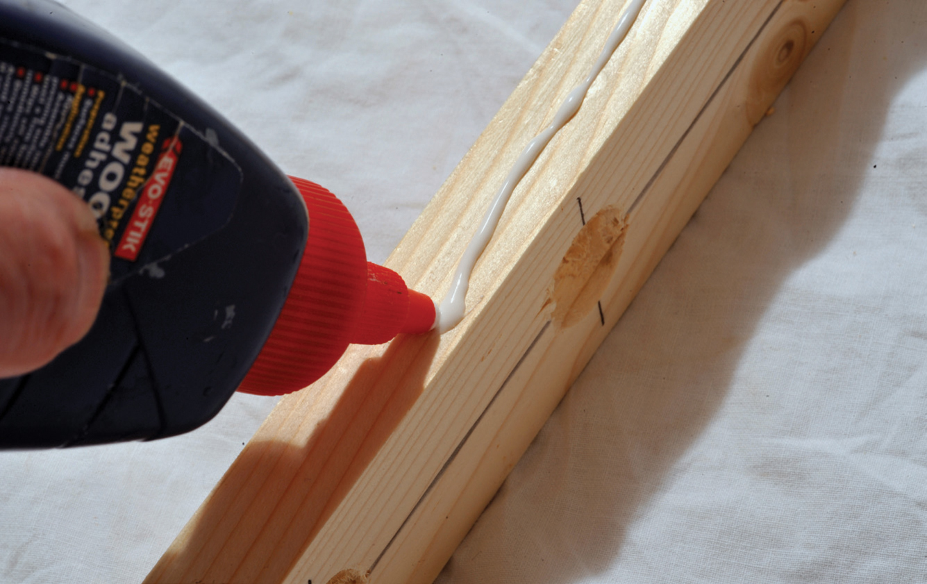
Gluing the frame.
Wipe away all excess PVA glue from both the outside and inside of the frame and baseboard, and finish with a damp rag. Lay face up on newspaper on a totally flat surface. Ideally, put weights on each corner and in the centre of the baseboard and leave to dry overnight. The following day, remove the weights and peel off any newspaper that has stuck. (If it does not come off cleanly, dampen it with warm water – this will soften the PVA and the paper can then be easily removed.) If you have to dampen it, allow it to dry before proceeding.

Lining up the corners on one side and inserting a screw in each corner of one side and one in the middle.
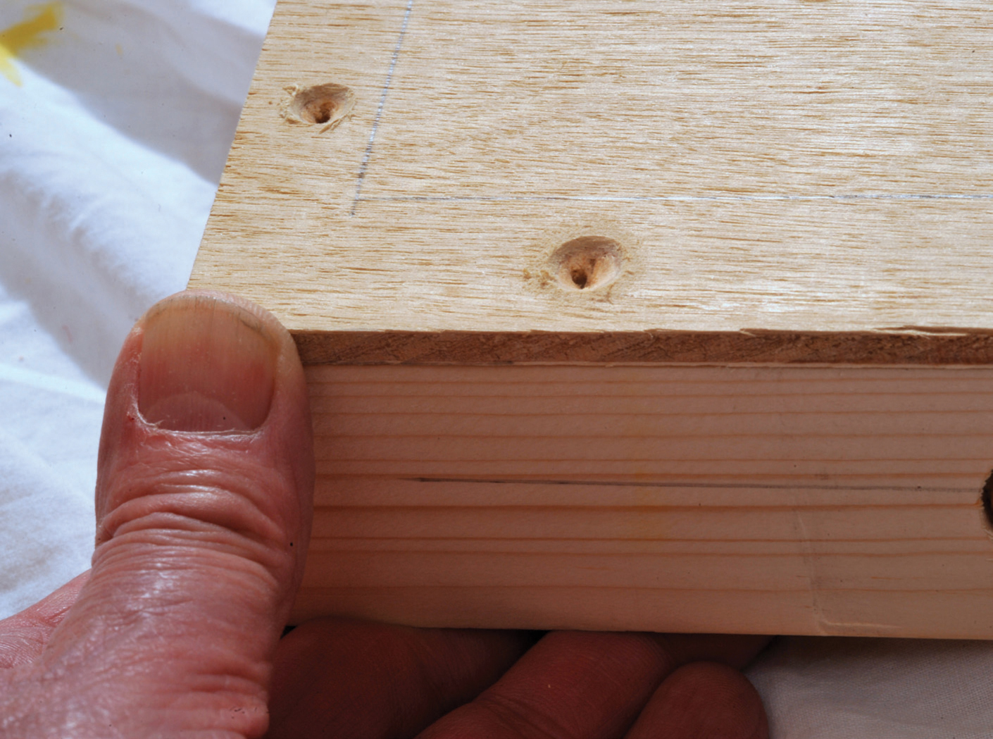
Pushing the frame to line up exactly with the baseboard top.
The next stage is to sand both the back and front of the board and all the sides and edges. You will probably have to use a medium grade at first, but always finish off with a fine grade. Wipe the whole board with a damp cloth to remove any remaining sanded wood particles. It is best to do the sanding at this stage, before you install the cross-members and spine, as it is much easier to sand down the underneath without the obstruction of the cross-members and spine.
Weighting the board down after gluing.
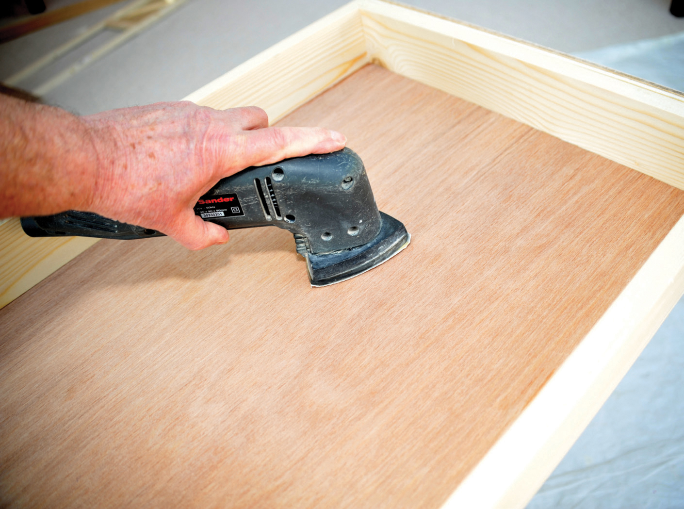
Using a detail sander to smooth the underneath before the cross-members are added.
The next stage is to install the cross-members. First, you need to lay your full-sized plan on the layout and mark where point motors and other items that could interfere with cross-members are located. For example, I will be installing pit head gear and this will hopefully be motorized. The last thing I want is either the spine or a cross-member being in line with the mechanics of the mine.
Remember that, as you are working on the reverse of the baseboard, you need to have your plan upside down as well. If you have drawn your track plan with a felt-tipped pen on lining paper or banqueting paper, you will be able to see the track plan through the paper. You do not need the detail, only sufficient to be able to set out the cross-members and the spine. Once all the key points are marked, work out where you would ideally locate the cross-members, usually about 300mm (12in) apart, and adjust the position of any that are close to points or other obstructions. Clearly mark these positions on the underside of the board with a felt-tip marker so that you do not use the wrong marks. Assuming that you have had your cross-members cut when having your baseboard sheet cut, and using either a chop saw or the 90-degree position on a mitre board and tenon saw, cut the 6mm (¼in) plywood cross-members to make a snug fit between the two sides. Bore very fine holes in the sides to correspond with each cross-member and insert fine pin nails so that the nail points are just protruding from each of the sides.
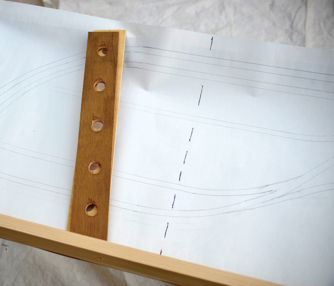
Wires are likely to have to pass through these cross-members and before installing you need to bore a series of holes to accommodate the wires. These holes can be made with a simple drill of about 16mm or with a spade drill. In either case you will be able to cut all of the cross-members at the same time. Place a spare solid piece of wood behind them and clamp all the cross-members to it. In making the holes this way you will have few splinters at the back of each cross-member. The same process applies for the spine pieces. If you have not already done so, sand down the cross-members so that they are free of any saw bits before gluing into place.
Place a layer of PVA glue along the line you have drawn on the underside of the baseboard and up the sides over the nails. (If you put the glue on the cross-member you will loose a percentage of it on to the back of the baseboard as you flex the cross-member when you push it into position.) Taking the cross-member, push it into the slightly protruding pin nails on one side and bend it into a slight bow whilst bringing the other end to make contact with the pin nails on the other side. Ensure that the pins are in the centre of the 6mm (¼in) plywood and that the whole length of the inner edge is in contact with the underside of the baseboard. Press down as hard as possible. Knock home the pin nails with a hammer and use a centre punch to sink them slightly into the wood. I usually have a couple of blocks of wood alongside the cross-member and balance tins of paint between the cross-member and the blocks of wood to hold it firmly in contact with the underside of the baseboard top until set. I usually also add a little more PVA along each side to complete the join and leave until dry. Repeat the process with the remaining cross-members. The other alternative is to use clamps to maintain contact between the spine and the underside of the baseboard.
Using the plan to determine the position of the cross-members in relation to track and points.

Using a set square to draw the cutting line.
Testing the ‘snugness’ of the fit before proceeding.
The position line of the cross-member and the pins in the side frame.
The holes are best cleaned with a finger wrapped in sandpaper.
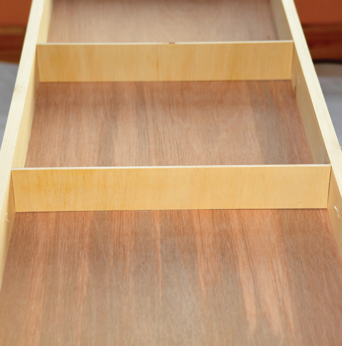
The cross-member pushed into the two pins of the frame and slotted into the correct position on the baseboard.
An alternative method of holding the cross-member with wood and weights.
The final stage is to install the spine. With the cross-members fixed in place, the spine has to be made up of several pieces, fitted between the end panels and the various cross-members. Cut each section carefully so that they are a tight fit. Put pin nails into the end panels, as before, but in the intermediate joints, glue is sufficient. Once dry, add a little more glue to make sure of a good fix. If you feel a little unsure about the quality of your joints, you can add sections of quarter-round and glue them into place. A simple clamp will hold these tight until the glue dries. Lay the whole board flat again and put weights on to each section of the spine until hard dry.
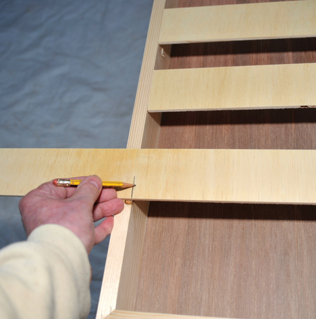
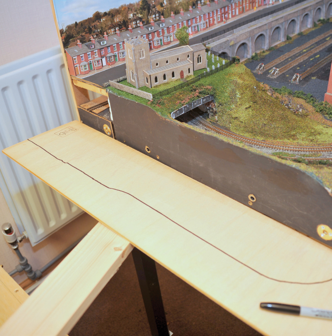
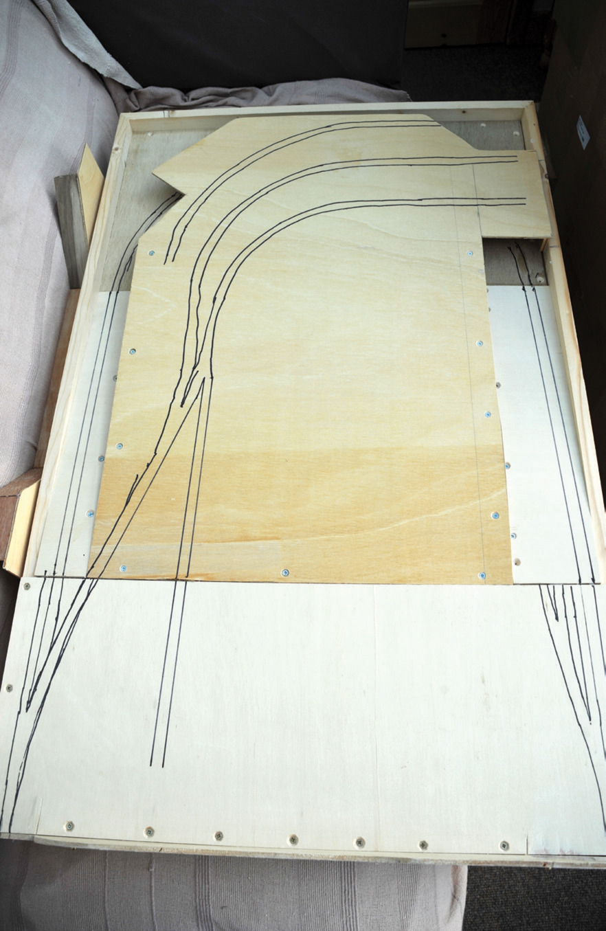
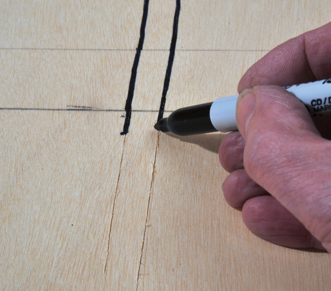
The basic construction of your flat-topped baseboard is now almost complete. With your track plan attached to the top of the baseboard, you need to transfer your track detail to the actual board. The best way is to take a scalpel or very sharp cutting blade and cut along the lines of the track marked out on the paper. You need to cut deeply in order to score the wood underneath. Not only will this leave you with a cut-out of the track, but also a baseboard that has been scored with the track layout. Take a felt-tipped pen and draw along the score lines. The pen will easily follow the slight cut in the wood – a slight wobble does not matter as it is only a guide as to the track plan.

Using a scalpel to mark out the track position on the baseboard. Cutting both removed the excess paper and scored the baseboard top.

Inking in the scored lines of the track.
One of the other boards being produced for this part of the book will be an alternative extension to my ‘N’-gauge layout ‘Pendleton Pit’. This new board will extend the length of the layout by a further 1,200mm (47¼in).
As I have said, the track in part is going to rise and, more importantly, fall. The maximum recommended gradient for track is 1:50, so in a length of 900mm (35½in) (allowing for a small level area just after the board join) the maximum height gain is about 18mm (¾in). For one track to pass under another there needs to be a minimum of 32mm (1¼in) clearance between the track and the upper ground level in ‘N’ gauge, so one track has to go up and one go down. Even then, I need to allow for the thickness of the board supporting the upper track, so it can only just be achieved. In fact the gradient will be very slightly greater on the downward slope than it will be on the upward slope, as trains and locos will cope with a greater downward slope better than they will a rising slope. This will allow me slightly greater clearance than space really allows, whilst not taxing locos on the ‘up’ slope.
In this situation working out the exact design in your head is somewhat difficult and to make it easier I always find it simpler to make up a card mock-up. Obviously the frame will still run round the outside of the baseboard, so it will be the full 1,200mm (47¼in) by 750mm (29½in). However, because there is a fall in the track at one end, the frame will have to be deeper. It would be possible to gradually increase the depth from one end to the other by cutting the two sides with a slight diagonal dropping from 44mm (1¾in) to the required 69mm (2¾in) depth, but it is far easier to make the frame in 18mm (¾in) by 69mm (2¾in) all round and to drop the perimeter track almost to the base level of the frame, at the same time as lifting the internal tracks above the height of the frame. Where the two boards join together, the tops of the frames are at the same height.
Making a multi-height board is far more challenging and time-consuming. I can only reiterate that, ideally, you should construct a flat baseboard before attempting boards with more than one level.
The concept was that there was to be a continuous track running round the perimeter, dropping from the standard level to pass underneath the upper track at the far end. This upper track was to be a terminus station. This was roughly sketched out but the next task was to work out the mathematics of the slope required. First, there needs to be a level section following the join and then a point to allow traffic to pass on to the upper or lower baseboard. The minimum length for this is 150mm (6in). The curved track at the lower level needs to be level for 200mm (8in). With a drop of 17mm (¾in) required to allow clearance for my ‘N’-gauge locos, the length required for the slope to create a gradient of 1:50 is 850mm (33½in). Adding the three measurements of 850mm (33½in), 150mm (6in) and 200mm (8in) gives an overall baseboard length of 1,200mm (47¼in). As clearance required for one track to pass under another is 34mm (1½in), the upper surface has to rise by 17mm (¾in). It is essential that this geometry is calculated before any work commences. It is only at this stage that a track plan can be produced to full scale.
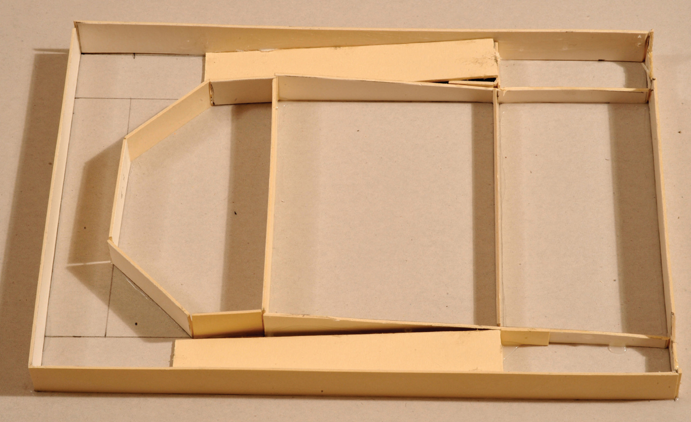
To be sure I have the concept worked out I always make a cardboard mock-up at 25 per cent of the full size: 190mm (7½in) × 300mm (12in). I use artist’s mountboard to make sample boards, as it is both rigid enough and easy to cut. Making a model to scale is far quicker, easier to adjust and cheaper than working in plywood. Making the model will show up all the problems that may occur and will also give you a guide as to possible material requirements.
As I have said, the outer frame for this baseboard will be constructed in 18mm (¾in) by 69mm (2¾in) softwood and this is made up in exactly the same way as the flat baseboard. The dowels are attached and the joining bolt holes are drilled before the board is constructed, so follow the instructions for dowels and bolts in the flat baseboard section. Also lay some track and add a coach to check clearances, as soon as the frame is made.
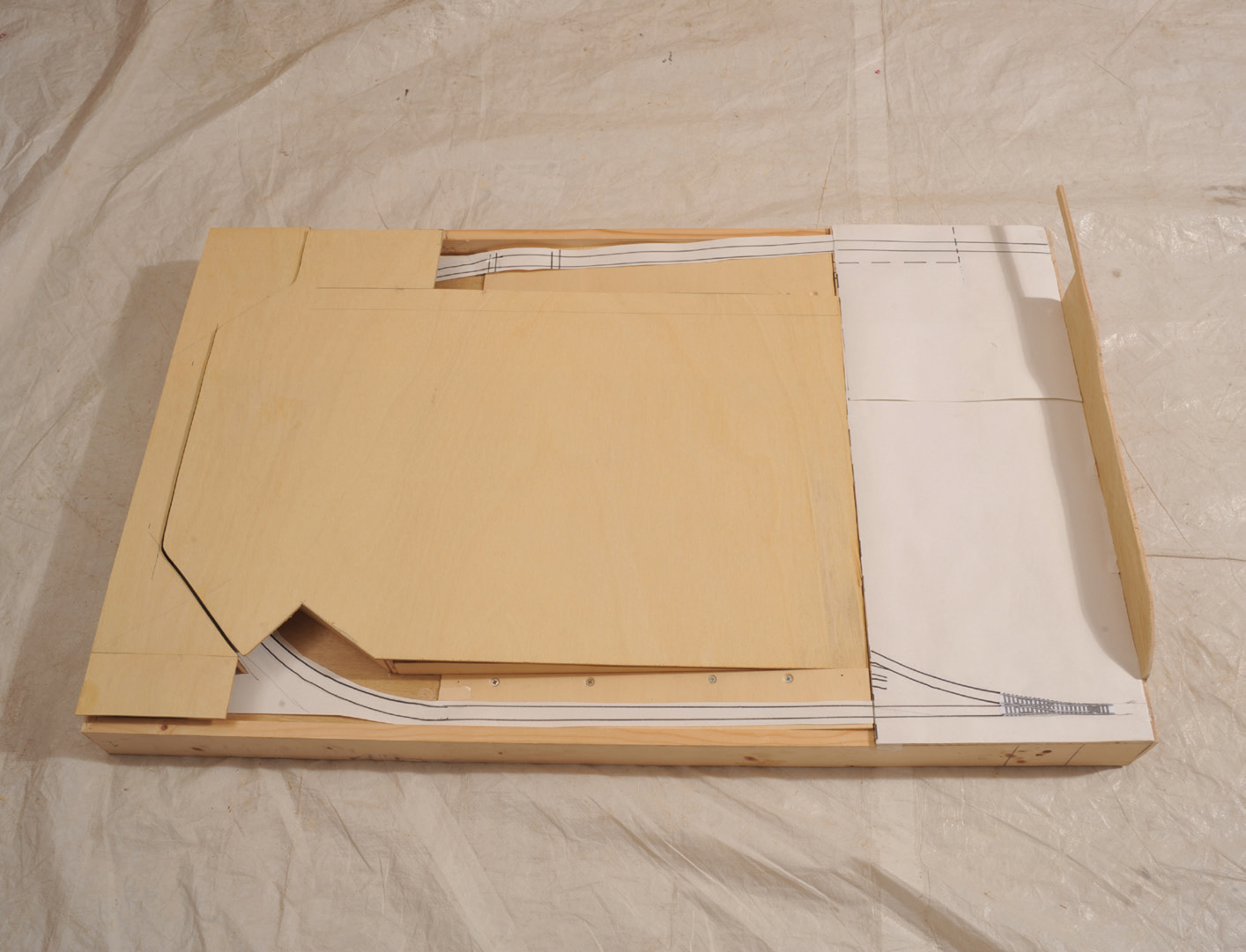
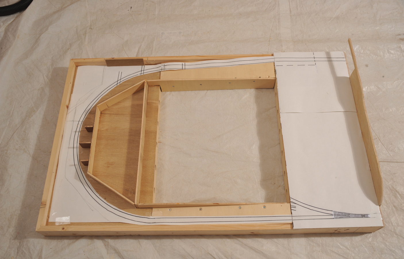
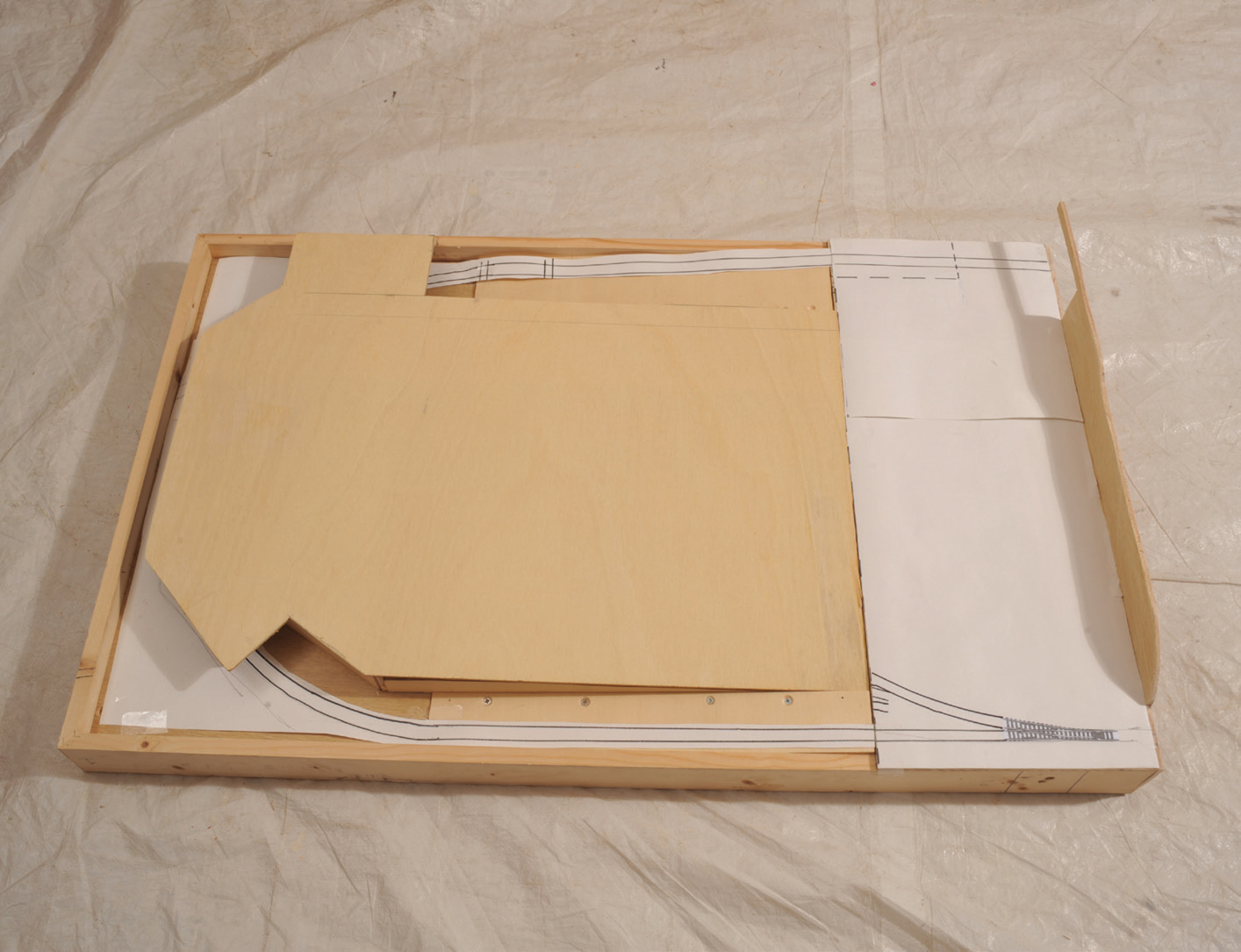
Full-scale plan laid on the finished baseboard.
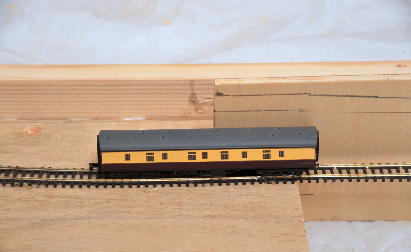
Practical clearance test once baseboard frame is completed – a coach on temporary track to ensure it passes under the top of the supports for the upper baseboard.
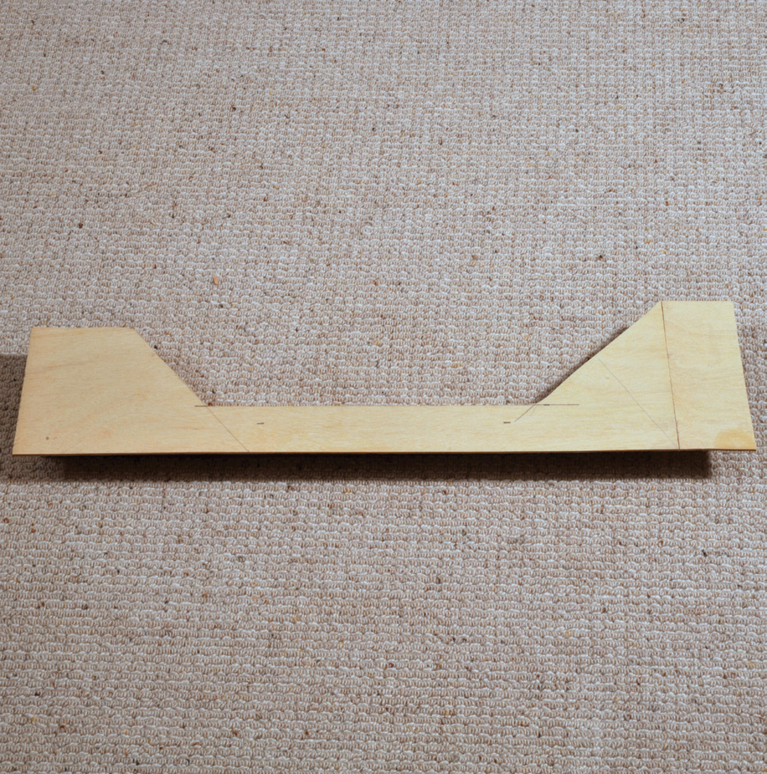
In my case this board will butt up to an existing board with scenery and this landscape will have to be matched with an end support. I have found that the best system is to draw out the contour of the scenery on to 6mm (¼in) plywood, cut this to shape, then screw and glue it to the end before cutting the final dowel and bolt holes. This partly made frame and baseboard is then checked by fitting to the existing baseboard to ensure that everything lines up perfectly.
With this sort of baseboard you still need to make up the outer frame first. As with a standard flat baseboard, you need to have at least a small, level piece of baseboard that will join up to the existing flat top to give a level join between boards, prior to starting the different slopes to vary the height. Using the pre-prepared track plan, and the initial calculations, I was able to calculate the size of board needed to create the flat area prior to having the large sheet cut to size.
Having made the frame, as described earlier, the next task is to fit this level area. This baseboard top is drilled, countersunk, glued and screwed in exactly the same way as for a flat baseboard, except that it only covers part of the frame.
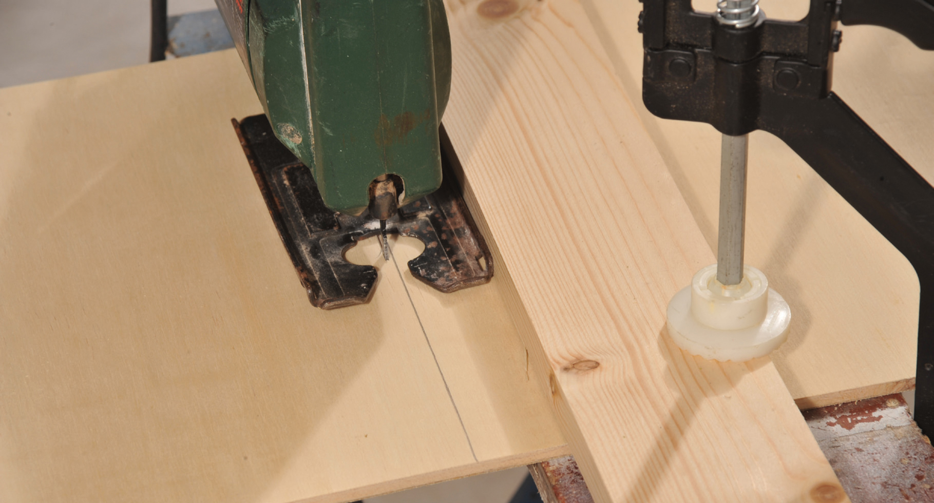
Once you have this baseboard top in place, you can begin to construct the lower level baseboard. This will also stretch across the whole width of the frame, but will only provide a base for the part of the track that is at the lowest level. Although I had the length cut out of the big 2,440mm (96in) by 1,220mm (48in) sheet, I needed to cut the width myself. I could have used a circular saw, but this tends to pull off parts of the plywood, leaving a slightly jagged finish. I prefer to use a jig saw with an extremely fine blade. To keep it in line, I position the saw blade on the line and then clamp a length of wood parallel to the line to be cut but in line with the side of the jig saw. By ensuring that the saw base is kept in contact with the wooden guide, it is possible to cut a perfectly straight line. In using a jig saw, the blade cuts on the up stroke and thus any bits that are chipped out are to be found on the top side. To achieve the best results, either cut from the underneath or add a second spare piece of plywood to supply support when cutting. A circular saw works in the exact opposite way, therefore the prime side should always be on top.
Drilling for dowels.

Dowel ready for insertion.
Cut end board and dowel hole pilot holes ready for drilling.
End board fitted and new board linked to master board of the model layout.
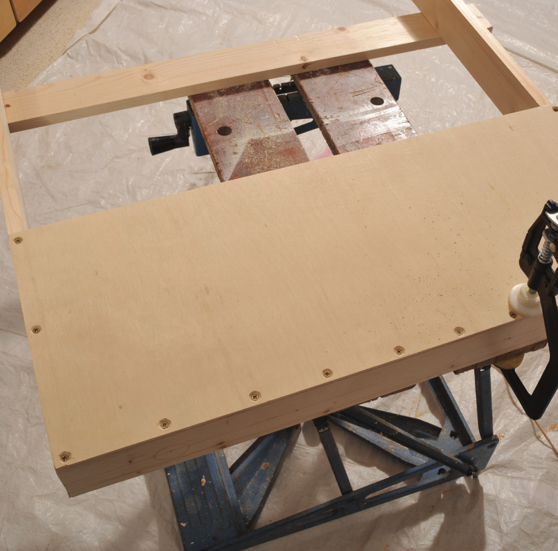
The top baseboard glued and screwed into place.
The lower baseboard has to fit inside the frame and needs cutting. A strip of wood is clamped to the board to be cut so that the plate of the jig saw can be held in a straight line.

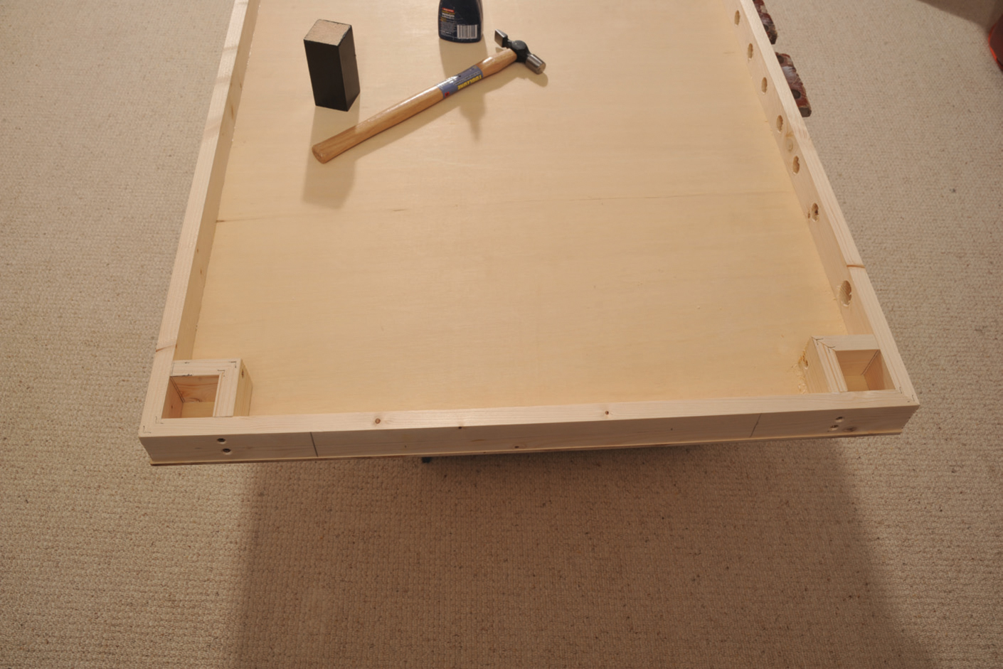
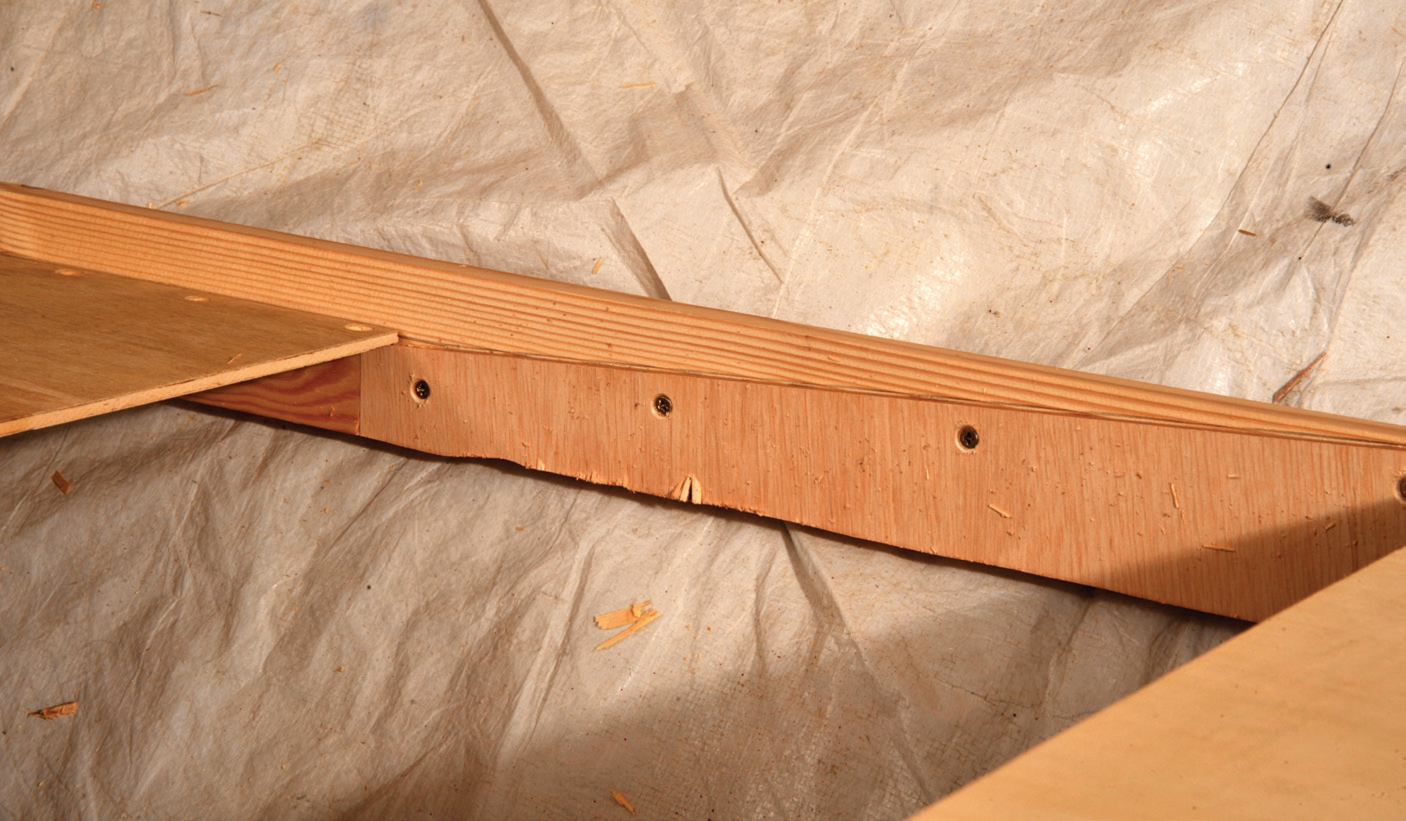
The bottom baseboard fitted on top of the sub-frame 40mm (1½in) from the bottom of the main frame.
The top of the lower baseboard needs to be located at 17mm (¾in) from the underside of the top baseboard. To achieve this with a 6mm (¼in) baseboard, you need to glue a sub-frame and cross-members 45mm (1¾in) from the bottom of the frame and then glue the lower level baseboard to the top of this sub-frame. The lower level baseboard will be cut to 664mm (26¼in) to fit inside the 700mm (27½in) external width of the frame (700mm/27½in less twice the frame thickness of 18mm/¾in = 664mm/27¼in and 200mm/8in long). This will help to make sure that the complete frame is exactly square.
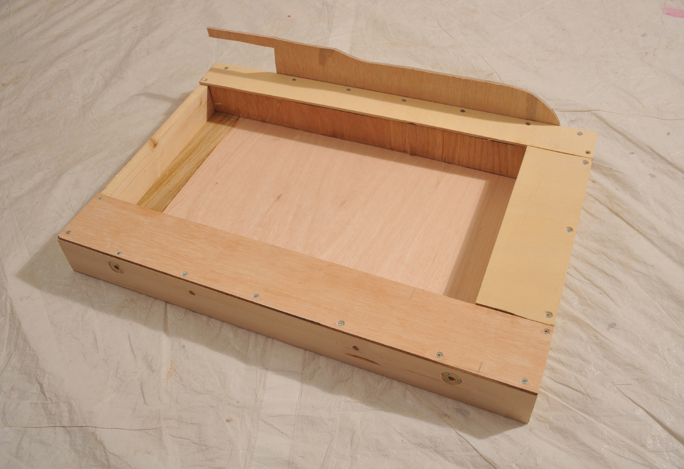
You now have a frame with two full-width baseboard tops, one is on the top and only a short length, the other is half-way down the frame at the other end, but both only stretch part of the length of the frame.
The track plan for this baseboard is similar to the flat baseboard. There is a track running round the outside, but this drops down from normal baseboard height, whilst the centre part is raised by a similar amount. This permits the lower track to lie underneath and hidden from the upper layer. On to this lower baseboard, having used the full-sized track plan to mark out the track, you need to install a series of roof supports to hold the upper level. These need to be 34mm (1½in) in height. From the model and the track plan you will be able to determine the positioning of the basic inner frames to support this roof/upper baseboard. Measure your various lengths of wood and cut them to size, making sure that, where it is possible, they stretch to the sides of the frame.

Cut out track plan to determine length and position of upper roof supports.
Roof supports glued into place.
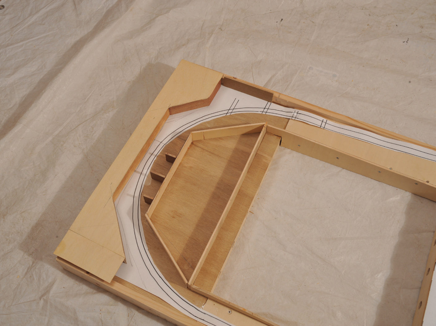
Having drawn out the plan of the outer circuit and the inner area tracks, the next stage is to construct slopes between the upper and lower baseboards. To form the slopes, you have cut four lengths of wood that will be level with the frame at the bottom but vary on the top from the full 69mm (2¾in), down to 45mm (1¾in). Two of these are glued directly to the frame and the ends are glued to the cross-member of both the upper and lower baseboard ends. The remaining two slopes are glued parallel to the frame to form the inner walls of the slopes between the two levels. (These sloping walls cannot be cut by a professional cutting service, as they are not horizontal or vertical, so they have to be cut by you.) They are fixed to the cross-members at the ends of the upper baseboard top at one end and the lower baseboard top at the other. To the top of these sloping inner walls, the track boards can be attached.
The support for the slope between the two levels showing the lower level baseboard in place.
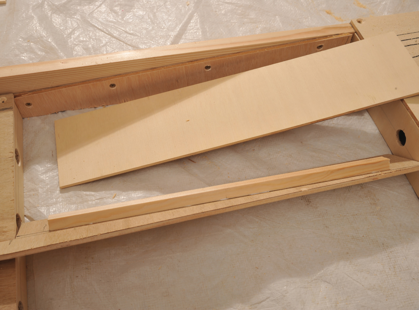
The boards to support the inside of the slope and the slopes themselves are cut to size.
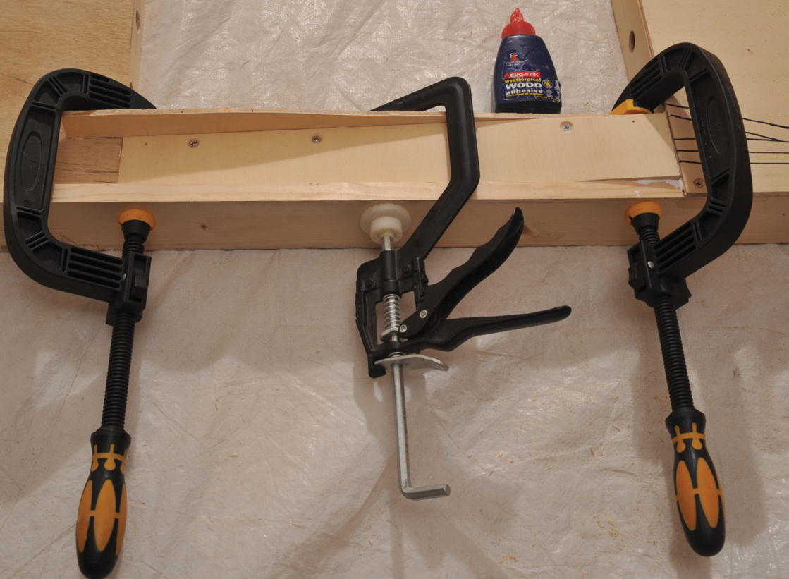
You now need to create a frame that will support the upward slope of the inner baseboard. This is most easily achieved by fixing 18mm (¾in) framing softwood to the inner side of the slope between the underside of the level baseboard end up to the level of the supports fitted to the lower baseboard at the other end. The upper baseboard is best made from 3.6mm (1/16in) plywood, as you can create a slight curve between the 1:50 slope and the level top with this thickness. Taking your full-sized plan, mark out the track, as previously described, before cutting, gluing and finally screwing it to the inner frame. It will take a little pressure to create the curve but, once screwed and glued, it will remain in place. To ensure firm contact of this flexed plywood, I use heavy weights (2 × 10-litre paint cans in this case).
The completed slope.
The upturned baseboard showing the softwood rails to support the upper baseboard.
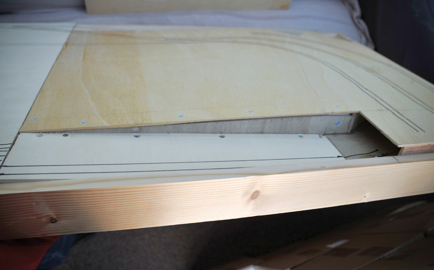
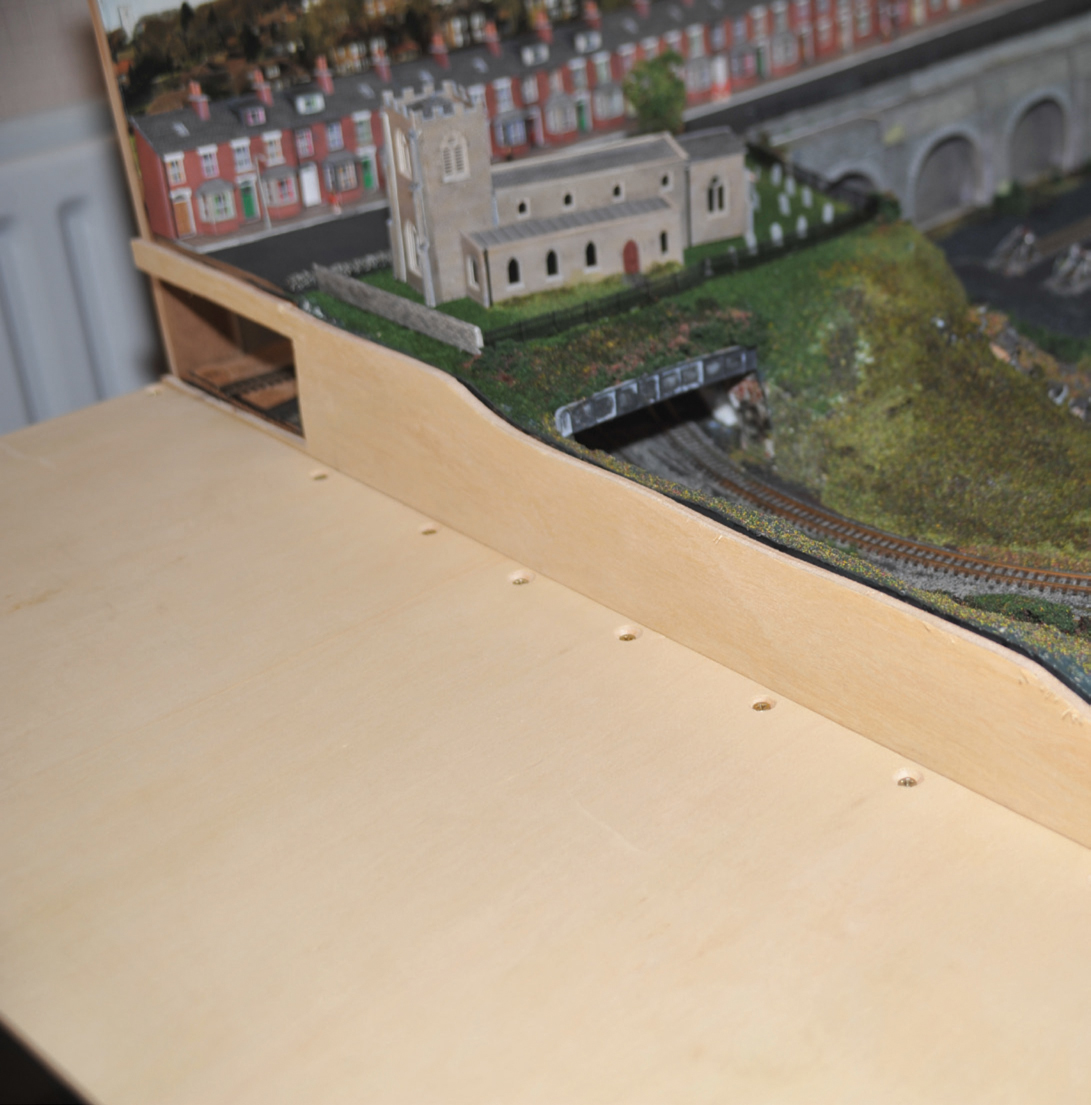
The upper baseboard showing the track markings. The slope to the lower level is also visible.
The one major problem with one track passing under another at a lower level is access. Provision for access needs to be made, otherwise it is almost guaranteed that this is where trains will derail or stop. I have created a removable section at the far end of the higher level and I designed the layout so that a platform will sit on top of most of the removable section with only a small piece of end track being included in the area to be removed.
Track drawn on baseboard with cut-away section to allow access to lower level.
The cut-away in place prior to fitting the top board.
Top board fixed but with cut-away removed.
As with the level board, the transfer of the paper layout to the track is achieved by cutting the paper with a scalpel knife along the track lines and then inking in the score marks on the plywood. The whole board, like the flat board, only needs sanding down and painting.
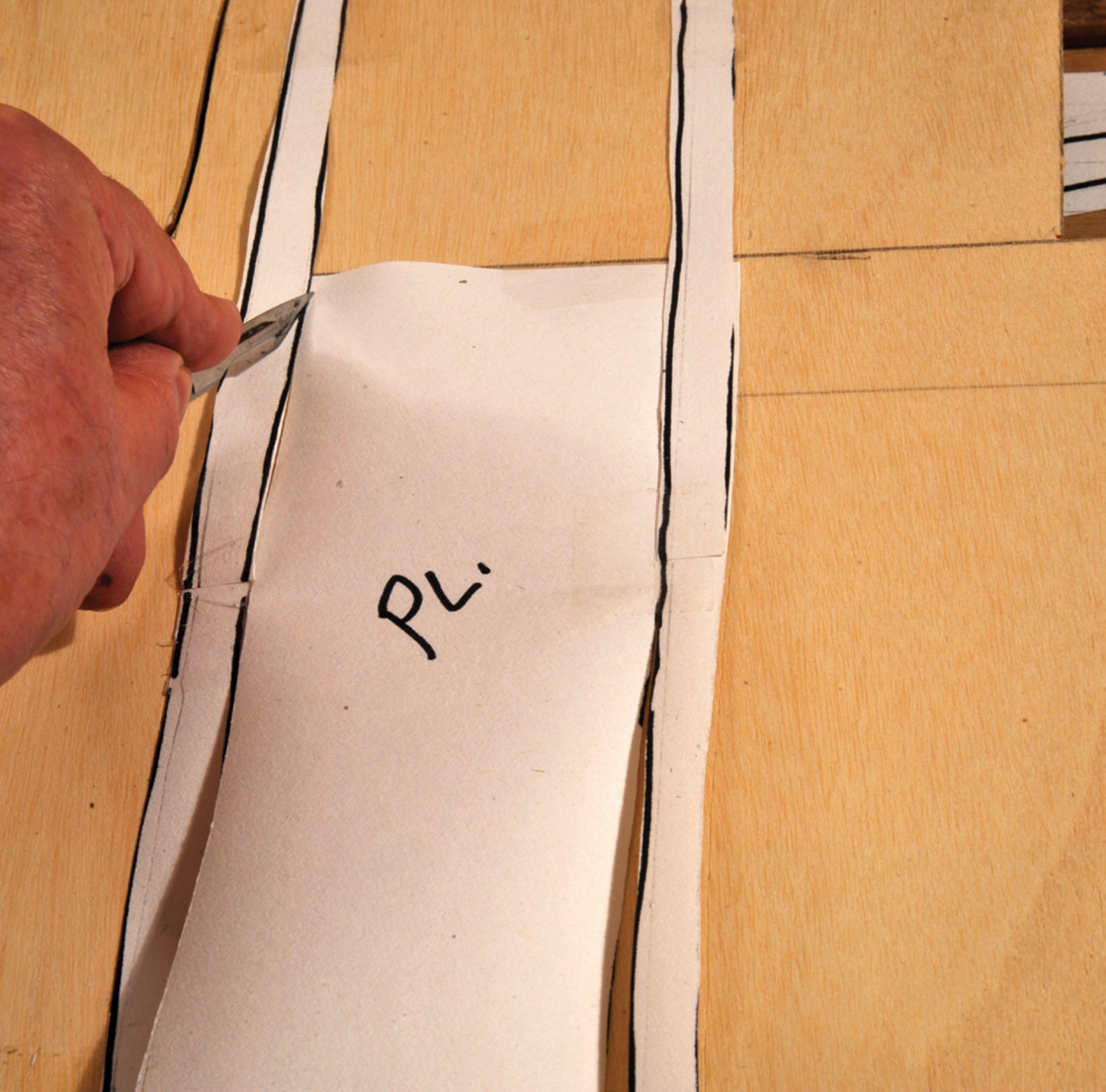
Transferring the plan to the board using a scalpel.
The cut out track showing only a small area of track is located on the cut out. This will be at the end of a station platform.
Transferring the track cuts to the board with a felt pen.
If we look at how railways were first constructed you appreciate that the land with all its lumps, bumps and depressions existed and the railway company had to create as level a track as possible across this terrain. Whilst the norm for many layouts is a totally flat base, larger layouts and many club layouts try to emulate real life. The hidden marshalling yards are usually kept at one level as they have no scenery and this area is purely functional, but as you come round from this level you can install a drop baseboard and then support the track off the ground, allowing the scenery to ebb and flow both below and above the level of the track. The other alternative, as I have described here, is to have a specific feature, such as a valley, which requires a dropped section. Due to space limitations I have just inserted a narrow (500mm/19¾in) dropped section, but there is no reason why that dropped area could not have been much bigger or even the full width of the visible area. The principles are the same. The drop should never start on the joint between two boards.
As far as I am personally concerned the drop baseboard has a twofold purpose. First, it provides an opportunity, if required, to extend my existing baseboards from 3,300mm (130in) to 3,800mm (149½in). Second, I have created a deep trough that will become a feature, with a steep-sided valley and a canal stretching from .back to front of valley with a canal lock which will hopefully simulate rise and fall of water in a canal lock.
As far as this book is concerned it demonstrates how to create a valley in a full-sized or smaller board. The makeup of the frame is the same as other boards and like the multi-level board, it uses a frame of 69mm (27¼in). It is the same depth from back to front 700mm (27¼iin) but only 500mm (20in) wide, as opposed to the 1,100mm (43in) main boards. I have made it this size as my railway room is only 4,000mm (157½in) long. I can fit three boards each of 1,100mm (43in) long plus a 500mm (19¾in) board along one wall and it can all be transported to exhibitions when required.
To bring the track across between the two adjoining boards there will be a small level area on each side before the valley. The tracks will traverse this valley, with an embankment at the front and a bridge at the back. The level areas at each end are 100mm (4in) at one end and 60mm (2½in) wide at the other, leaving a valley of 340mm (13½in). Having had these pieces cut to the correct size, I have screwed and glued both to the frame. To support the level areas I have added 57mm (2¼in) deep cross-members (the cross-member will fit under the 6mm/¼in) baseboard top and have the 6mm (¼in) lower baseboard attached at the other end, making 69mm (2¾in) in total). These cross-members are located at the ends of the two short baseboards, as this is where the valley will begin. These form the vertical walls of the valley. These were glued and then clamped in position and left to dry overnight. The base of the trough is constructed from a sheet of 6mm (¼in) plywood, bringing the overall depth to 69mm (2¾in) – the same as the frame. This is glued to the two crossmembers and the two frame edges exactly in line with the base of the frame. This creates a vertical sided wooden ‘well’, which will be infilled with sloping sides and the canal at the modelling stage.
This completes the basic structure of the drop baseboard. Like all the other baseboards described in this book, it obviously needs sanding down and varnishing to produce the finished baseboard ready for modelling.

The drop baseboard frame being held in place until the glue dries.
The completed 500mm (19½in) board with both a level run-on and a level run-off with the centre drop, which will become a valley, with a bridge carrying the track at the back and an embankment at the front.
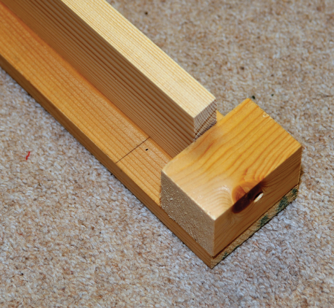
Open-topped baseboards tend to be used where there are varying track levels and where there is only a minimal amount of track. Once again it is essential that you have a detailed track plan, so that you can work out the different heights of the track supports and the pattern required for the cross-members, before you begin. The plan must be to cut each cross-member from a single piece of plywood and in doing so to allow for both the planned design of the track(s) and the various heights. Obviously there is a slight loss in rigidity, as there is no overall baseboard top to hold the construction firmly. I would always recommend using a softwood frame. This is constructed in the same way as described for the flat-topped baseboard. When gluing it together, greater care has to be taken to ensure that all the corners are at 90 degrees, as you do not have a rectangular top to ensure accuracy. The final gluing can still be achieved by clamping each corner to a flat sheet of professionally cut wood. When dry, I prefer to add a small block of wood into each corner. I suggest that the minimum size should be 44mm (1¾in) by 44mm (1¾in) for the full depth of the frame.
The next stage is to add the cross-members in the same way as described earlier. The big difference is that the cross-members need to be cut to the correct height to support different track levels by using either a fret saw or a jig saw to cut the crossmember to predetermined heights. You will need slightly more cross-members to support the track than you would with a flat baseboard. Each cross-member must stretch the full width of the frame and they must be fitted vertically to provide maximum rigidity. Once in position and thoroughly dry, you need to insert the spine between the cross-members and the frame. Depending on the width of the board, you may need two spines.
You should now have a rigid frame with its spine and cross-members ready for the next stage. With an open board you are not installing a baseboard top, but you are fixing track beds for all the tracks. It is usually necessary to use a jig saw or a fretsaw, as tracks are unlikely to be straight lines. Each of the track beds is glued and either pin-nailed or screwed to each cross-member. Once all the track beds are in place, the skeleton of the frame will still be visible in many areas. These gaps are covered over with scenery or buildings made as part of the landscaping of the board. Once all the woodwork is complete, the board will require sanding and finishing.
The open baseboard with the contours cut into the cross-members and the only areas supported are the track beds where the three tracks will run.
Insulation board such as ‘Celotex’ can be used in certain situations. Some modellers push material uses to the extreme, but in this book I am limiting uses to the practical side. Insulation board is extremely light – a sheet of 50mm (2in) × 2,440 (96in) × 1,220 (48in) board can be picked up with two fingers. It has the disadvantage that it can be easily damaged. It is not cheap to buy, being slightly dearer that the equivalent size in 6mm (¼in) plywood. It was first used in the USA, where layouts tend to be much bigger and have longer track runs without points and signals. For those exhibiting their layouts with long runs and few points, such boards have a tremendous weight advantage. Track can be easily pinned or glued and pinned, but fixing point motors means either cutting a chunk out of the polystyrene-type foam and fixing the point directly to the track, or having surface point-motors.
The sides and ends of insulation boards need protection and if you have more than one board, they need to be joined together accurately. These boards, therefore, need a wooden frame to be constructed to your chosen size. This frame is constructed in the same way as with the standard baseboard fame. Cutting Celotex insulation board (or any other make) is easy. It can be achieved with a standard hand saw or a tenon saw, or even a serrated bread knife. The Celotex should be cut very slightly oversize (about 2mm) and glue applied to the sides of the frame – the glue must be ‘Gripfix’ or something similar, which does not dissolve the foam. The foam can then be squeezed into the frame, as it has a very small amount of flexibility. Use a length of flat wood rested on the Celotex and push (or use a mallet) to force home the Celotex. If you do not use something that spreads the load, you could crack the sheet. It is then possible to fit pattern makers’ dowels into the wooden frame and, although you cannot fit bolts to join the boards, you can fit toggle catches to the frame (see Chapter 10). As there is no strength in the insulation board it is usual to support such boards on trestles, with supports running between them, or tables. Unless weight reduction is crucial, or unless you just wish to experiment, I would personally not recommend the use of insulation boards. The weight saving between a 6mm (¼in) top with 6mm (¼in) cross-members and the weight of Celotex is not that great as to make any crucial difference.
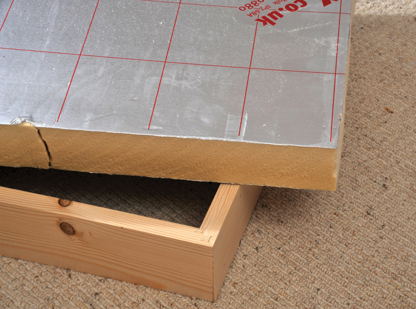
Insulation board 50mm (2in) and its frame.
Using a tenon saw to cut insulation board – note the lack of bits compared with cutting polystyrene.

The pre-glued frame with insulation board squeezed into it. Note that the frame is glued around the top of the upright so that as the Celotex is pushed home, it spreads downwards. If the Celotex had been glued, all the glue would have remained on the surface due to the tight fit.

The completed board.
In several clubs and national organizations, there are some groups who wish to work cooperatively to produce personally designed individual boards that join together to make a much larger layout. The key to such projects is a master set of end patterns that allow individuals to produce their own board, knowing that, having used the standard end pattern to fit the joining dowels, both the tracks and the baseboards will line up exactly with any other baseboard in the same scheme. Probably the most well-known is ‘FREMO,’ a large international group of railway modellers who organise meetings all over Europe. The individual personal layouts all have the same end plates and, therefore, will join together in any combination at an exhibition. Their longest layout is reported to be 1.2km. Further information on the organization is available on www.fremo-net.eu.
Most clubs, when building a multi-board layout, will use a standard end pattern so that all boards are the same and could be put together in a variety of ways. The ‘OO’ section of my own club has planned a new exhibition layout, but as a result of moving to new premises, has decided to use the fiddle yards at each end only for exhibitions and replace them with alternative boards to create a continuous circuit for club use. Likewise the ‘N’-gauge section of the club is also building a new layout, which can be expanded for display at exhibitions by the addition of two 1000mm (39in) boards both in the back and the front of the layout. (Unlike the ‘OO’-gauge section this will be continuous running for exhibitions and within the club – it will just be longer at exhibitions!) These developments will not be possible without standard end plates. Whilst we can design our own unique end panels, many members are also members of the local ‘N’ Society group who are also planning cooperative board construction. Both groups have investigated having a pattern made in metal, so that all members can drill their own boards to exactly accurate predetermined holes, but the normal costs of a metal pattern are high and there is a general feeling that if a national manufacturer was prepared to market a reasonably priced standard end panel for a variety of widths, e.g. 450mm (17¾in), 600mm (23½in) and 700mm (28in) wide, there would be a considerable market across many societies and clubs, and possibly the creation of a national standard. In the meantime, an alternative is to use a wooden pattern. The pattern has to fit on the edge of a board so that its pre-drilled hole or holes are both at the same height from the top of the board and the same distance from the ends. A simple ‘T’ constructed in 18mm (¾in) by 69mm (2¾in) softwood (or hardwood), with an end stop and a single hole, will provide such a pattern. The only use of the pattern is to accurately position the centre of the dowel holes (and bolt holes if used). The actual drilling of the holes to accommodate the plate of the dowel is all based on the pilot holes. The design of this pattern means that it can be turned round to allow use on both corners and, no matter which way round the board is used, the dowel holes will marry up exactly. By fitting a male dowel to the front of the end panel and a female dowel to the rear of the end panel, boards can be interlinked.
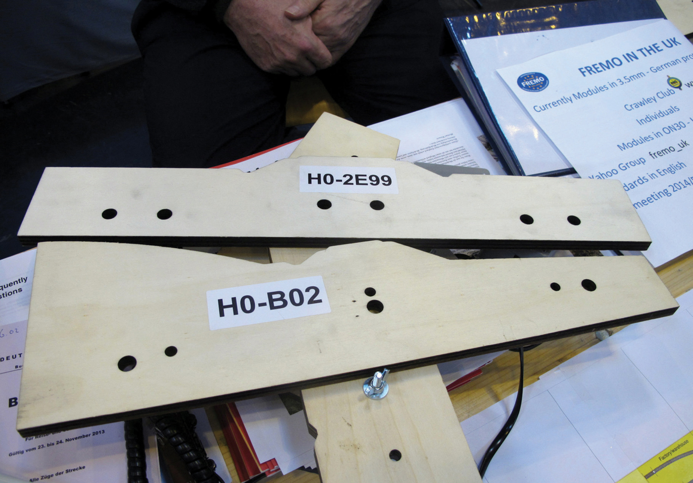
A sample set of ‘FREMO’ end jigs.
A homemade wooden jig with its end stop. The central board allows the jig to fit both left- and right-hand end boards.
The jig placed over the end of a baseboard.
The pilot hole at the front of the jig. (There is a second hole towards the rear.)
Layouts in lofts, specific railway rooms or ‘dens’ will often be end-to-end layouts. Many modellers prefer layouts that have continuous running. Taking a layout in a shed, for example, it is possible to have a track running from one side of the door to the other, with each end being much wider to allow the track to curve back on itself. In this way you get continuous running and free access into the centre of the layout. The alternative is to have a hinged or removable flap to permit access. It may also be that the layout is sufficiently high so that the owner and visitors are able to duck under the layout, but this is less popular as you get older.

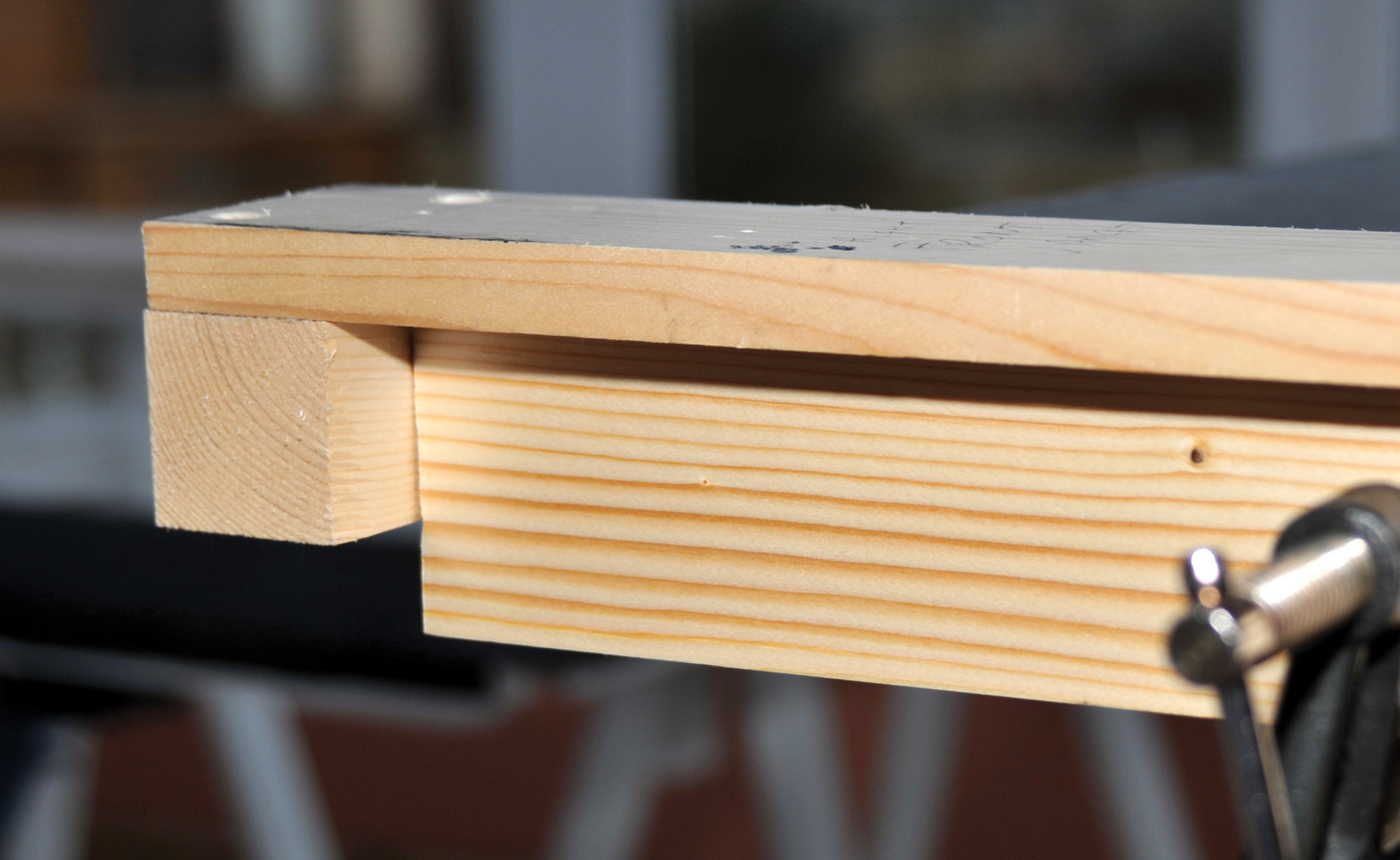
The additional end plate attached to the baseboard. The ends are chamfered to prevent catching clothes on a sharp corner.
Hinged flaps obviously rely on a hinge. There are specialist bar hinges, which have to be cut into the worktop, but they still have some flexibility in the opposite end and need to have a method of ensuring that the track is 100 per cent lined up each time. Hinged flaps are very heavily used and over a period of time can become a little slack. The best system is a drop-in section. The frame of the section needs to be very rigid and it is probably best to use 44mm (1¾in) square timber for the frame, covered in 6m (⅛in) plywood to create the baseboard.
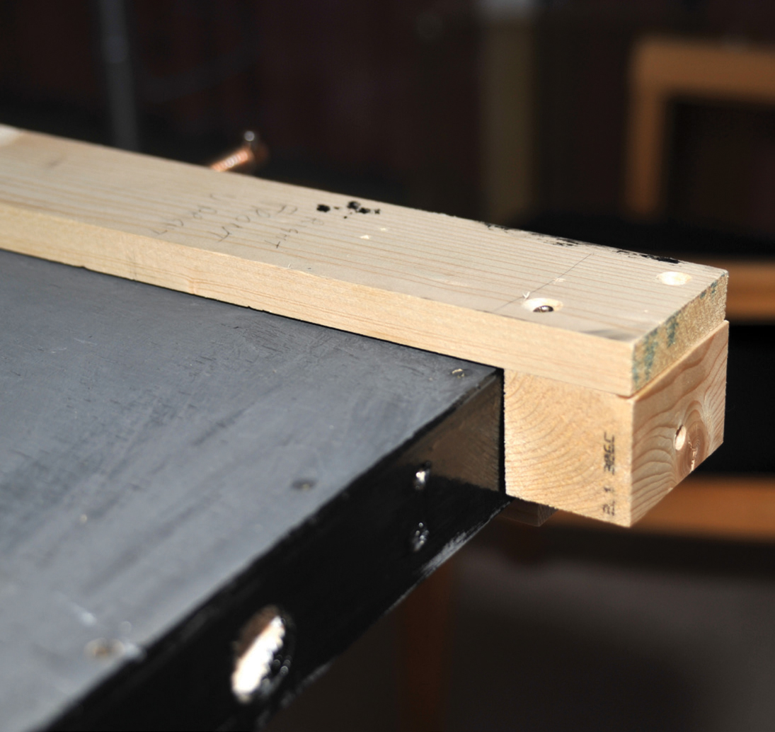
The two main baseboard ends need to have lips added to support the drop-in section. These need to be 34mm (1¼in) by 44mm (1¾in) to provide sufficient strength and rigidity. The lips need to be glued and screwed to the layout ends at a level that is 50mm (2in) below the baseboard surface (to accommodate the depth of the drop in frame and its baseboard).
The width of 44mm (1¾in) is essential. To ensure complete registry between tracks on the drop-in section and the main baseboard ends you need to fit furniture-makers’ dowels. These are not fitted to the sides, but to the bottom of the drop-in section and the top of the lips. As they need to be an exact register, it is best to either drill both the shelf and the drop frame before they are fixed, or use a standard jig. As the tracks are laid after fitting, you only need to be concerned with the height of the drop-in section in relation to the main baseboards and lining up the edges of both with the drop-in section. Once complete, the drop-in section can be easily lifted out and dropped back in with certainty that the tracks will line up. To provide even more stability it is sensible to use toggle clamps so that the section cannot inadvertently be removed.
Dowels are inserted in the top of the end plate and the bottom of the flap. Be careful to position the two frames correctly before drilling. One will be upside down.
The new flap fitted on to the chamfered end plate to create a level join.
There has been a tendency in the last few years for a series of novelty baseboards to be produced, usually with a very simple oval with one siding. An old computer monitor case has been used containing a Wild West scene. A bigger layout is contained in a car roof top box, which opened up to provide lighting and a reasonably complex layout. This can be closed up easily and fitted back on the roof of the car for transporting back home. A multitude of small aluminium or other rigid material suitcases also appear at some shows, with a variety of layouts and scenery. Each layout and baseboard has to be designed for each situation. All three examples have flat baseboards supported to a suitable height for viewing.
There are many variations of novelty baseboards which are seen at shows. Some have been produced for specific competitions, but others have been purely for a weekend project. It can make a change for a serious modeller to have fun occasionally and it certainly causes comment from the exhibition viewing public.
Having reached almost the end of the chapter, you will have constructed your baseboard in whatever design you have chosen. The first task, before proceeding further, is to check that all the joints and seams are well-glued, adding a little extra glue where it has not fully taken. You will need to double check that all the screws are tight and that all the pin nails are tapped fully home, using a centre punch.
At some stage you will probably be adding a mixture of water and PVA to various parts of your layout on the baseboard. Much will depend on the type of layout being planned for the board. You need to both sand and seal the board to stop the ingress of any water into any of the joints (remember most PVA glues are still water soluble)
Further information on finishing is contained in Chapter 9.
By now you have all the information you need to construct a wide range of baseboards. The choice is obviously yours, depending on your skills and the availability of tools. It is important that you use the instructions given regarding the flat baseboard as the basic for the construction of many other types of board, as the basic information is not repeated for each board. I have assumed that you have read the book thoroughly before starting to work on your board.
If you take your time and follow the instructions, creating a simple baseboard is not beyond the scope of most railway modellers. If you feel it is beyond your capabilities, you may find someone at your local club who can assist.
In Chapter 15 you will find instructions on building a very simple baseboard with legs that requires only glue and a screwdriver and a local DIY centre to do all your cutting. Personally, it is not a board I would recommend unless you are really stuck, as it is a little ‘clunky’ and heavy, but it will do the job if you do not have the skill or the courage to build a more complicated board or the funds to buy a commercial one. If I did not have the skills I would prefer the board described in Chapter 15 to a second-hand one off the internet.
If all else fails, there are manufacturers of model railway baseboards who sell either completed boards or boards in kit form, which require the minimum of skill to produce a satisfactory baseboard. Chapter 14 gives more details and Chapter 15 concentrates on constructing the simplest baseboard of all, for which you only need a screwdriver and some glue.