23
CHAPTER
Gas Ranges and Ovens
Gas ranges, ovens, and cooktops are designed on the basis of using the heat generated by combustion to cook the food. The types of fuels that feed gas appliances are:
• Natural gas Natural gas is lighter than air and has a heating value between 900 and 1200 BTUs.
• Liquefied petroleum (LP or LPG) LP gas is heavier than air and has a heating value between 2500 and 3200 BTUs.
• Mixed gas Mixed gas is lighter than air and has a heating value between 700 and 900 BTUs.
• Manufactured gas Manufactured gas is lighter than air and has a heating value between 500 and 700 BTUs.
To sustain combustion in a range, oven, or cooktop, an ignition source, such as a flame or by electrical means, is used to ignite the gas vapors. To ignite these gases, the temperature will have to be between 900 and 1200 degrees Fahrenheit.
The pressure of natural gas that is supplied to a residence will vary between a five- and nine-inch water column. LP or LPG gas pressure for residential appliances, as established by the gas industry, will be between a nine- and eleven-inch water column. To determine the correct pressure rating, the technician must refer to the manufacturer’s specifications or the installation instructions for that product. The two most common types of gas used in homes are LP and natural gas.
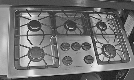
On some models, electricity (120 volts) is supplied to the gas appliance for ignition, temperature control, safety valve, electronic controls, and accessories (clock, lights, etc.). Gas cooking appliances are available in a wide variety of styles also. Figures 1-1, 1-4, and 23-1 are just a small sampling.
FIGURE 23-1 A five-burner gas cooktop with sealed burners.
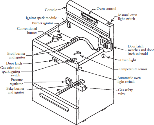
This chapter will provide the basics needed to diagnose and repair gas cooking appliances. Figure 23-2 identifies where components are located within the gas range. This illustration is used as an example only. The actual construction and features might vary, depending on the brand and model you are servicing.
FIGURE 23-2 The locations of components in a gas freestanding range.
Principles of Operation
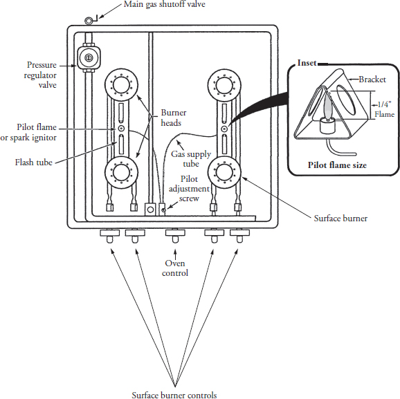
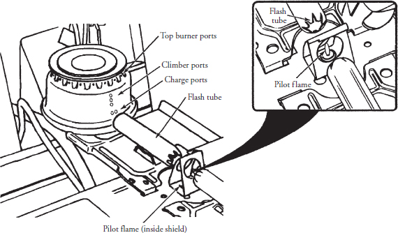
When the gas is turned on (standing pilot ignition system), whether by a knob or automatically by a control device, gas will begin to flow from the supply line through a gas pressure regulator into the gas manifold for distribution to the burners or to the oven safety valve (Figure 23-3). The gas travels from the manifold through the controls, passing through the orifice into the venturi throat and mixing tube. The air-gas mixture then enters the burner head, exits through the burner ports, and travels through the flash tube to the pilot flame (Figure 23-4). Once ignited, the flame begins to travel back through the flash tube to the charge ports and climber ports and burns evenly around the burner head.
FIGURE 23-3 A top view of a standing pilot ignition system, illustrating the component locations in a freestanding gas range. See inset for pilot flame height.
FIGURE 23-4 The air-gas mixture is traveling through the burner ports and flash tube, encountering the pilot flame and igniting the burner.
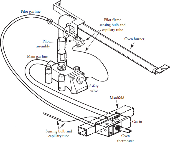
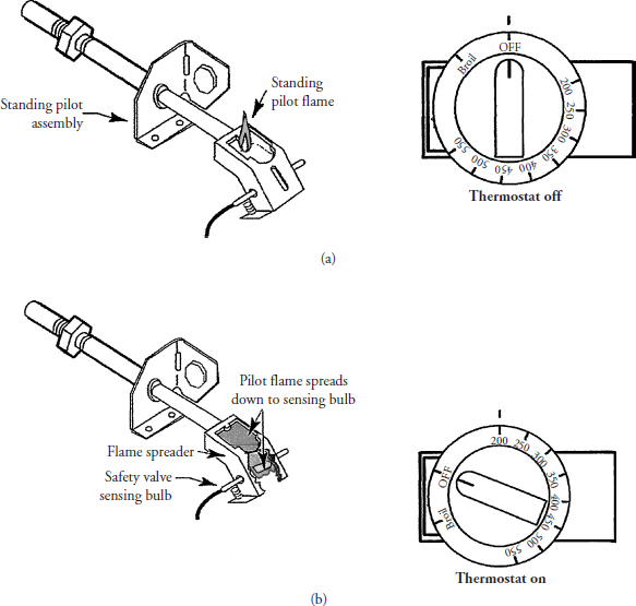
When the oven thermostat is turned on, gas flows from the manifold (Figure 23-5) through the thermostat and to the safety valve. The thermostat also feeds gas through the pilot gas line to the pilot assembly. The pilot flame will increase in size, heating the safety valve-sensing bulb (Figure 23-6), opening up the safety valve and allowing gas to flow to the burner. When the air-gas mixture flows out of the oven burner, it encounters the pilot flame and the burner ignites. When the oven cavity temperature is satisfied, the gas flow will stop to the oven burner and the gas flow to the pilot assembly will decrease to the standing pilot light.
FIGURE 23-5 The components that make up the oven burner system with a standing pilot ignition system.
FIGURE 23-6 When the thermostat control knob is in the “off” position, the pilot flame stands up. With the thermostat control knob turned on, the pilot flame will increase in size, heating the safety valve-sensing bulb.
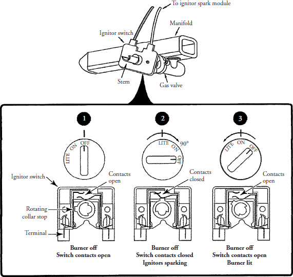
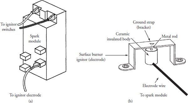
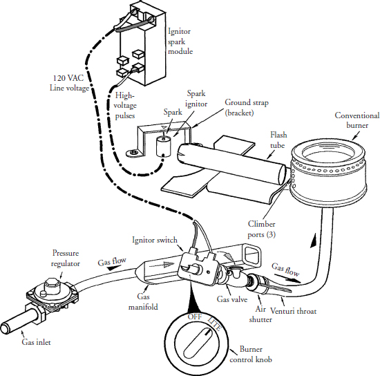
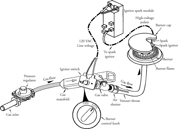
On models with electronic ignition, the standing pilot is replaced with ignitor switches, surface burner electrodes, and a spark module (Figures 23-7, 23-8, 23-9, and 23-10). When the consumer turns the burner control knob to the “lite” position, a switch within the ignitor switch will close, supplying 120 volts through the ignitor switch to the spark module. Some spark modules will produce a high-voltage pulse to the ignitor every two seconds at very low amperage (4 milliamps). Some models use a spark module that will produce two to three sparks per second. This pulse will produce a spark between the ignitor electrode and the ignitor-grounding strap (see Figure 23-8). At the same time, the gas will begin to flow from the supply line through a gas pressure regulator into the gas manifold for distribution to the burners. When the burner is lit, the control knob will then be turned to the “on” position, where the height of the flame can be adjusted. When this occurs, the switch within the ignitor switch will open, turning off the voltage to the spark module (see Figure 23-7).
FIGURE 23-7 The electronic ignition switch is mounted over the surface burner valve stem. 1. When the knob is in the “off” position, the contact switch is open and there is no gas flow. 2. The knob is set in the “lite” position, the contact switch is closed, and gas flows to the burner. 3. When the knob is turned to the “on” position, the ignitor switch will open, breaking the circuit, and gas flows to the burner.
FIGURE 23-8 (a) A typical spark module. (b) The surface burner ignitor and grounding bracket.
FIGURE 23-9 The components that make up the standard burner system using an electronic ignition system to light the burner.
FIGURE 23-10 The components that make up the sealed burner system using an electronic ignition system to light the burner.
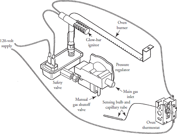
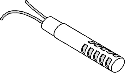
When the oven thermostat is turned on and set to the desired temperature, a switch contact from within the thermostat will close. This action will complete the circuit, supplying 120 volts to the glow-bar ignition system (Figure 23-11). The glow-bar ignitor (Figure 23-12) must heat up to 2000 degrees Fahrenheit, allowing 2.5 to 4.0 amps to flow to the safety valve. As the bimetal warps, the safety valve will open, allowing the gas to flow through the orifice into the venturi throat and mixing tube. The air-gas mixture then enters the oven burner head, exits through the burner ports, and travels to the glow-bar ignitor, igniting the oven burner. Once ignited, the flame begins to burn evenly around the burner head. The entire process takes about 60 to 90 seconds to complete.
FIGURE 23-11 The components that make up the oven burner system using a glow-bar ignition system to light the burner.
FIGURE 23-12 A typical glow-bar ignitor.
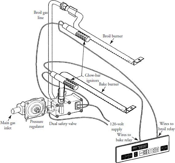
The self-cleaning operation in a gas range is similar to that of the electric range (see Chapter 22). The only difference is that some models use two burners (Figure 23-13). The broil burner allows the consumer to broil food in the same oven cavity. In the self-cleaning mode, both burners do not come on at the same time. As Figure 23-13 shows, the burners are controlled by the electronic control to operate the dual safety valve and the glow-bar ignitors. When the oven cavity temperature reaches 600 degrees Fahrenheit, the door latch lock light will come on, locking the oven door and preventing the consumer from opening it. When the oven cavity temperature stabilizes (between 840 and 920 degrees Fahrenheit), the cleaning process begins. This cleaning process requires approximately two to three hours. When the self-cleaning cycle is complete, the burners turn off and the oven begins to cool down. When the oven cavity temperature drops below 600 degrees Fahrenheit, the oven latch lock light will go off, allowing the consumer to open the oven door.
FIGURE 23-13 The components that make up the self-cleaning oven system using two glow-bar ignitors to light the burners. The consumer can bake or broil in the same oven cavity.
Safety First
Any person who cannot use basic tools or follow written instructions should not attempt to install, maintain, or repair any gas range, oven, or cooktop. Any improper installation, preventive maintenance, or repairs could create a risk of personal injury or property damage.
If you do not fully understand the installation, preventive maintenance, or repair procedures in this chapter, or if you doubt your ability to complete the task on your appliance, please call your service manager.
The following precautions should also be followed:
• Always follow the use and care guide instructions from the manufacturer.
• Never use a range to heat the home; it simply was not designed for that purpose.
• Keep the cooking area clean of soot, spills, and grease.
• Do not use flammable liquids near a cooking appliance.
• When repairing the range, always use the proper tools.
• Always reconnect the wires to the range after repairs have been made.
• Before servicing any gas components in the range, turn off the gas supply.
• Always have a fire extinguisher nearby in case of mishaps that might lead to a fire.
• Make sure that gas appliances have proper venting according to the manufacturer’s recommendations.
• To eliminate personal injury or fire when operating the appliance, avoid using the storage cabinets above the product.
Before continuing, take a moment to refresh your memory of the safety procedures in Chapter 2.
Do not store any flammable materials near a gas appliance, and avoid ignition sources in the event you smell gas leaking. Make sure you have proper ventilation when servicing the gas appliance to prevent carbon monoxide (CO) poisoning.
Gas Ranges, Ovens, and Cooktops in General
Much of the troubleshooting information in this chapter covers gas ranges, ovens, and cooktops in general, rather than specific models, in order to present a broad overview of service techniques. The illustrations that are used in this chapter are for demonstration purposes only to clarify the description of how to service these appliances. They in no way reflect on a particular brand’s reliability.
Location and Installation of Gas Range, Oven, and Cooktop
Locate the range, oven, or cooktop where it will be well lighted and have access to proper ventilation. The range must be level for proper baking and cooking results. The range might be installed adjacent to the left and/or right base cabinets and against a rear vertical wall (for the “anti-tip” cleat). A wall oven must be installed on a supporting surface that is strong enough to support the weight of the oven and its contents while remaining level from side to side and from front to rear. A cooktop must be installed on a flat surface, supported by the countertop, and it should be level. Contact your flooring company to check if the flooring can withstand a minimum of 200 pounds. It is also recommended that you contact your builder to determine if the cabinets and walls can withstand the heat produced by the gas appliance. Some kitchen cabinets and building materials were not designed to withstand the heat that is given off by the product.
The proper installation instructions for your model are included with the appliance. These instructions will assist you with the installation requirements (dimensions, electrical requirements, cutout dimensions, venting, etc.) needed to complete the installation according to the manufacturer’s specifications.
Some gas appliance models are equipped with electronic controls and electronic ignition. The electrical plug that is considered for use must be properly polarized and grounded in order for the electronic controls to function properly. The appliance chassis must also be grounded so that the electronics in the product will function properly.
Step-by-Step Troubleshooting by Symptom Diagnosis
When servicing an appliance, don’t overlook the simple things that might be causing the problem. Step-by-step troubleshooting by symptom diagnosis is based on diagnosing malfunctions, with their possible causes arranged into categories relating to the operation of the gas cooking appliance. This section is intended only to serve as a checklist to aid you in diagnosing a problem. Look at the symptom that best describes the problem that you are experiencing with the range, oven, or cooktop, and then proceed to correct the problem.
Gas Odors
• Check the pilot light.
• Check for a gas leak in the supply line.
• Check the ventilation system.
• Check the burner controls. When not in use, the controls must be completely turned off.
• Check the regulator.
Surface Burner Will Not Light
• Check the pilot light.
• Check the pilot burner port holes for a blockage.
• Check for 120 volts to the appliance. Check fuses or circuit breakers.
• On electronic models, check the ignition system.
• Check the burner openings for a blockage.
• Check the air-gas mixture.
• Check for a blockage in the gas supply to the appliance and burner.
• Make sure that the gas supply is turned on.
The Pilot for the Surface Burner Will Not Stay Lit
• Check the burner for blockages.
• Check the setting and adjust the pilot light.
• Check the air-gas mixture.
• Check for a blockage in the gas supply to the appliance and burner.
• Check for a wind source that may affect the pilot light.
The Surface Burner Flame Is Too Low
• Check the burner assembly for blockages.
• Check the air-gas mixture.
• Check for a blockage in the gas supply to the appliance and burner.
• Test the gas pressure to the appliance and make corrections, if necessary.
• Check and make sure that the range/oven is converted to the correct gas type (LP or natural).
The Surface Burner Flame Is Too High
• Check the air-gas mixture.
• Test the gas pressure to the appliance and make corrections, if necessary.
• Check and make sure that the range/oven is converted to the correct gas type (LP or natural).
• Check the pilot light. If the pilot is too small, adjust the height.
• Check the control settings on the clock or electronic controls.
• Check for 120 volts to the appliance.
• Check the ignition system.
• Check the fuses in the appliance.
• Check the glow-bar ignitor.
• Check the selector switch, thermostat, and the safety valve for proper operation.
• Check for a blockage in the pilot light.
• Test the gas pressure to the appliance and make corrections, if necessary.
• Check and make sure that the range/oven is converted to the correct gas type (LP or natural).
• On electronic models, check for unusual display readouts and/or error codes.
Oven Temperature Will Not Hold
• Check the oven temperature and thermostat control.
• Check for a blockage in the oven burner.
• Check the oven door and gasket.
• On electronic models, check for unusual display readouts and/or error codes.
Self-Cleaning Function Is Not Working
• Check the controls for the proper settings.
• Check the door latch assembly. Make sure the latch engages.
• Check the thermostat and the selector switch for proper operation.
• Check for 120 volts to the appliance.
• Check the door alignment and gasket.
• On electronic models, check for unusual display readouts and/or error codes.
The Burner Orifice Squeals
• Check the orifice opening for debris.
• Make sure that the correct orifice size is in use.
• Test the gas pressure to the appliance and make corrections, if necessary.
Supply Air Is Noisy
• Check the venturi throat and mixing tube for debris and rough edges.
• Check the burner positioning over the orifice.
Erratic Burner Flame
• Check the gas pressure at the gas regulator.
• Check the burner controls for proper operation.
Yellow or Sooty Burner Flame
• Make sure that the burner is in the correct position.
• Check the air-gas mixture.
• Test the gas pressure to the appliance and make corrections, if necessary.
Gas Appliance Maintenance
To maintain gas appliances, always follow the manufacturer’s recommendations for periodic maintenance as stated in the use and care manual. The range, oven, or cooktop can be cleaned with warm water, mild detergent, and a soft cloth on all cleanable parts, as recommended in the use and care manual. Also, never use abrasive cleaners that are not recommended by the manufacturer.
Do not allow grease spillovers to accumulate on top of the range after cooking; they will become a fire hazard. When cleaning the burners, always make sure that all of the portholes are free of debris. If, for any reason, the burner portholes are blocked, the flame appearance will be different. Blocked portholes will reduce gas flow and the heating valve of the burner will be reduced.
Repair Procedures
Each repair procedure is a complete inspection and repair process for a single range, oven, or cooktop component, containing the information you need to test a component that might be faulty and replace it, if necessary.
Any person who cannot use basic tools should not attempt to install, maintain, or repair any electric dryer. Any improper installation, preventative maintenance, or repairs will create a risk of personal injury, as well as property damage. Call the service manager if installation, preventative maintenance, or the repair procedure is not fully understood.
Gas Burner Valve
The gas burner valve is mounted on the manifold and it supplies gas to the burners.
The typical complaints associated with the burner valve are:
• It is hard to turn on.
• When the gas burner valve is on, little or no gas comes out.
• There is a gas smell around the burner valve.
• Unusual display readouts and/or error codes.
To handle these problems, perform the following steps:
1. Verify the complaint. Verify the complaint by testing for gas leaks. Next, turn on the burners. Is the pilot light on? Are the electronic switches working?
2. Check for external factors. You must check for external factors not associated with the appliance. Is the appliance installed properly? Are there 120 volts to the appliance? The voltage at the receptacle is between 108 volts and 132 volts during a load on the circuit. Do you have the correct polarity? (See Chapter 6.) Is the gas turned on?
3. Disconnect the electricity. Before working on the appliance, disconnect the electricity. This can be done by pulling the plug from the electrical outlet. Or disconnect the electricity at the fuse panel or at the circuit breaker panel. Turn off the electricity.
WARNING Some diagnostic tests will require you to test the components with the power turned on. When you disassemble the control panel, you can position it in such a way that the wiring will not make contact with metal. This act will allow you to test the components without electrical mishaps.
4. Shut off the gas supply. Before you begin servicing any gas components, shut off the supply of gas to the appliance. The shutoff valve should be within 6 feet of the gas appliance.
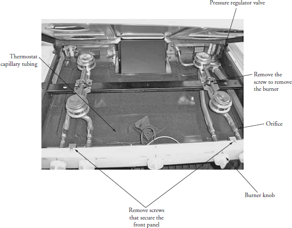
5. Gain access to the gas burner valve. To gain access to the gas burner valve, lift the cooktop, pull off the control knobs, and then remove the screws from the front panel (Figure 23-14). Remove the control panel. This will expose the gas burner valve and manifold (Figure 23-15).
FIGURE 23-14 A top view of the components in an electronic ignition system.
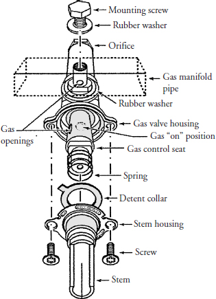
FIGURE 23-15 An exploded view of the surface burner valve.
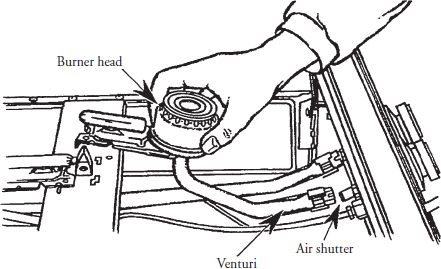
6. Remove the gas burner valve. To remove the gas burner valve, remove the screw that secures the burner to the burner bar, and then lift the burner head up and out of the range (Figure 23-16). With the gas burner valve still attached to the gas manifold, remove the orifice with a wrench, turning it counterclockwise. Now remove the gas burner valve by removing the mounting screw that is secured to the manifold right above the valve (see Figure 23-15). Remove the valve. On some models you might have to completely remove the manifold from the range in order to remove the screw that secures the valve to the manifold.
FIGURE 23-16 To remove the surface burner, remove the screw that secures the burner to the burner bar, and then lift the burner head up and out of the range.
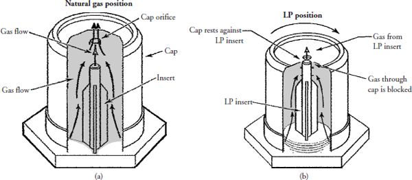
7. Install a new gas burner valve. To install a new gas burner valve, just reverse the disassembly procedure, and reassemble. Be careful not to damage the washers when reinstalling the gas burner valve (see Figure 23-15). Most gas ranges, ovens, and cooktops have universal orifices. When you remove the orifice, you must reinstall that orifice for the type of gas supplied to the range. For natural gas, the orifice must be tightened down clockwise about two to three turns, making sure that the gas LP insert rests against the orifice cap, then unscrew counterclockwise the orifice cap about two and a half turns (Figure 23-17a). For LP gas, the orifice will tighten down only two and a half times, resting against the gas LP insert (Figure 23-17b). If the orifice is tightened down too much the gas flow will be restricted. Reinstall the front
FIGURE 23-17 (a) The universal orifice in the natural gas position. (b) The universal orifice in the LP position.
Ignitor Switch
The ignitor switches (four) are wired in parallel and mounted on each burner valve stem. These switches are rotary-actuated (Figure 23-7). The ignitor switches control the 120 volt supply voltage to the spark module by opening and closing the circuit.
The typical complaints associated with the ignitor switch are:
• The ignitor switch is hard to turn on.
• The surface burner will not light.
• Unusual display readouts and/or error codes.
To handle these problems, perform the following steps:
1. Verify the complaint. Verify the complaint by turning on the surface burners. Do any of the burners come on? Do you hear or see the ignitors sparking? Are the ignitor electrodes clear of debris? Is there good contact between the ignitor bracket and the burner bar? On electronic models, turn off the electricity to the appliance and wait for two minutes before turning it back on. If a fault code appears, look up the code. If the range/oven will not power up, locate the technical data sheet behind the control panel or for diagnostics information. On some models you will need the actual service manual for the model you are working on to properly diagnose the range/oven. The service manual will assist you in properly placing the range/oven in the service test mode for testing the range/oven functions.
2. Check for external factors. You must check for external factors not associated with the appliance. Is the appliance installed properly? Are there 120 volts to the appliance? The voltage at the receptacle is between 108 volts and 132 volts during a load on the circuit. Do you have the correct polarity? (See Chapter 6.)
3. Disconnect the electricity. Before working on the range or cooktop, disconnect the electricity to the appliance. This can be done by pulling the plug from the receptacle. Or disconnect the electricity at the fuse panel or at the circuit breaker panel. Turn off the electricity.
WARNING Some diagnostic tests will require you to test the components with the power turned on. When you disassemble the control panel, you can position it in such a way that the wiring will not make contact with metal. This act will allow you to test the components without electrical mishaps.
4. Shut off the gas supply. Before you begin servicing any gas components, shut off the supply of gas to the appliance. The shutoff valve should be within six feet of the gas appliance.
5. Gain access to the ignitor switch. To gain access to the ignitor switch, lift the cooktop, pull off the control knobs, and then remove the screws from the front panel (see Figures 23-7 and 23-14). Remove the control panel to expose the ignitor switches.
6. Test the ignitor switch. Remove the wires from the ignitor switch terminals. Set your ohmmeter to the R x 1 scale; reinstall the surface burner knob on the gas valve. Place the ohmmeter probes on the ignitor switch terminals. With the burner knob in the “off” position, the ohmmeter should read no continuity. Turn the burner knob to the “lite” position; the ohmmeter should read continuity. If your readings differ, replace the ignitor switch.
7. Install a new ignitor switch. To install a new ignitor switch, remove the screws that secure the ignitor switch, reverse the disassembly procedure, and reassemble. Turn on the electricity and the gas supply, and test the surface burner. On some models, the ignitor will produce between two and three sparks per second. On electronic models, make sure to take the range/oven out of the service test mode when the repair is completed.
Surface Burner Ignitor
A surface burner ignitor is a metal rod with a ceramic insulating body that is wired to a spark module. Electrical pulses from the spark module cause the surface burner ignitor to arc to the ground strap, which is mounted above the ignitor. These sparks will ignite the surface burner. On a gas range there are two ignitors to light the four surface burners.
The typical complaints associated with the surface burner ignitor are:
• The surface burner will not light.
• Only one surface burner ignitor is working.
• Intermittent operation of the surface burner ignitor.
• Unusual display readouts and/or error codes.
To handle these problems, perform the following steps:
1. Verify the complaint. Verify the complaint by turning on the surface burners. Do the burners come on? Do you hear or see the ignitors sparking? Are the ignitor electrodes clear of debris? Is there a good ground contact between the ignitor bracket and the burner bar? If all of the ignitors are sparking, check for a shorted ignitor switch. On electronic models, turn off the electricity to the appliance and wait for two minutes before turning it back on. If a fault code appears, look up the code. If the range/oven will not power up, locate the technical data sheet behind the control panel or for diagnostics information. On some models you will need the actual service manual for the model you are working on to properly diagnose the range/oven. The service manual will assist you in properly placing the range/oven in the service test mode for testing the range/oven functions.
2. Check for external factors. You must check for external factors not associated with the appliance. Is the appliance installed properly? Are there 120 volts to the appliance? The voltage at the receptacle is between 108 volts and 132 volts during a load on the circuit. Do you have the correct polarity? (See Chapter 6.)
3. Disconnect the electricity. Before working on the range or cooktop, disconnect the electricity to the appliance. This can be done by pulling the plug from the receptacle. Or disconnect the electricity at the fuse panel or the circuit breaker panel. Turn off the electricity.
WARNING Some diagnostic tests will require you to test the components with the power turned on. When you disassemble the control panel, you can position it in such a way that the wiring will not make contact with metal. This act will allow you to test the components without electrical mishaps.
4. Shut off the gas supply. Before you begin servicing any gas components, shut off the supply of gas to the appliance. The shutoff valve should be within six feet of the gas appliance.
5. Gain access to the ignitor. To gain access to the ignitor (see Figure 23-8), lift up the cooktop (see Figure 23-14). The ignitor is located on the burner bar, between the two burners’ flash tubes.
6. Test the ignitor. Set your ohmmeter on R x 100. Test the ignitor bracket to ground; the meter should indicate continuity. Disconnect the ignitor electrode wire and test for continuity.
7. Install a new ignitor. Remove the screws that secure the ignitor bracket to the burner bar, and disconnect the ignitor electrode wire. To reinstall the ignitor, just reverse the disassembly procedure, and reassemble. Test for a good ground between the ignitor bracket and the burner bar. Turn on the electricity and the gas supply, and test the surface burners. The ignitor should produce two sparks per second or, on some models, two to three sparks per second. On electronic models, make sure to take the range/oven out of the service test mode when the repair is completed.
Spark Module
The spark module is located in the rear of the range or underneath the cooktop on a cooktop model. Whenever the spark module is energized by the ignitor switches through an ignitor cable, a solid-state circuit and pulse transformer within the module housing will send electronic pulses to both surface ignitors at the same time. The spark module operates at very low amperage (4 milliamps). The high-voltage pulses or sparks present no severe shock hazard to the consumer or to the service technician.
The typical complaints associated with the spark module are:
• You hear a “clicking” noise but the surface burner will not light.
• You hear an erratic “clicking” noise from the surface burner ignitor.
• You do not hear the “clicking” noise and the surface burner will not light.
• Unusual display readouts and/or error codes.
To handle these problems, perform the following steps:
1. Verify the complaint. Verify the complaint by turning on the surface burners. Do the burners come on? Do you hear or see the ignitors sparking? Are the ignitor electrodes clear of debris? Is there good contact between the ignitor bracket and the burner bar?. On electronic models, turn off the electricity to the appliance and wait for two minutes before turning it back on. If a fault code appears, look up the code. If the range/oven will not power up, locate the technical data sheet behind the control panel or for diagnostics information. On some models you will need the actual service manual for the model you are working on to properly diagnose the range/oven. The service manual will assist you in properly placing the range/oven in the service test mode for testing the range/oven functions.
2. Check for external factors. You must check for external factors not associated with the appliance. Is the appliance installed properly? Are there 120 volts to the appliance? Does the electrical outlet have the correct polarity? The voltage at the receptacle is between 108 volts and 132 volts during a load on the circuit. Do you have the correct polarity? (See Chapter 6.) Is the gas to the appliance turned on?
3. Disconnect the electricity. Before working on the range/oven or cooktop, disconnect the electricity to the appliance. This can be done by pulling the plug from the receptacle. Or disconnect the electricity at the fuse panel or at the circuit breaker panel. Turn off the electricity.
WARNING Some diagnostic tests will require you to test the components with the power turned on. When you disassemble the control panel, you can position it in such a way that the wiring will not make contact with metal. This act will allow you to test the components without electrical mishaps.
4. Shut off the gas supply. Before you begin servicing any gas components, shut off the supply of gas to the appliance. The shutoff valve should be within six feet of the gas appliance.
5. Gain access to the spark module. You can access the component by removing the back panel (see Figure 22-9). Locate the spark module (see Figure 23-8).
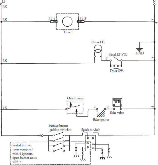
6. Test the spark module. Before you test the spark module, test the surface burner igniter electrodes and the surface burner igniter switches first. Next, check the grounding strap on the ignitor. Now, check the ignition system wiring for a short or loose wiring. If they test okay, proceed to test the spark module (Figures 23-8 and 23-18). Set your voltmeter on the 120-volt scale. Remove the L1 wire from the spark module, and attach one of the meter probes to that wire. Attach the other meter probe to the neutral terminal on the spark module. Next, turn on the electricity to the appliance, turn on the surface burner control knob to the “lite” position, and test for 120 volts. The voltmeter should read 120 volts. If it does not, check the wiring connections and wiring. After checking the wiring and connections, if you still do not have the ignitors sparking, then replace the spark module.
FIGURE 23-18 A typical wiring schematic for a range with electronic ignition.
7. Remove the spark module. With the electricity turned off, disconnect the wiring terminals from the spark module one at a time and label them. Remove the screws that secure the spark module to the appliance.
8. Install a new spark module. To install the new spark module, just reverse the disassembly procedure, and reassemble. Be sure that you install the wires onto the correct terminals according to the wiring diagram for the product you are servicing. Turn on the electricity and gas supply, and test the surface burners. Make sure that the spark at the ignitor has a sharp blue appearance. This indicates a good working ignition system. On electronic models, make sure to take the range/oven out of the service test mode when the repair is completed.
Glow-Bar Ignitor
The glow-bar ignitor is constructed of a silicon-carbide material. When 120 volts is applied to the glow-bar, it heats up to about 2000 degrees F. As the temperature increases, its resistance decreases, allowing 2.5 to 4.0 amps to flow to the safety valve.
The typical complaints associated with the glow-bar ignitor are:
• The oven/broiler will not light.
• The glow-bar ignitor is on but, the oven/broiler burner will not ignite.
• Unusual display readouts and/or error codes.
To handle these problems, perform the following steps:
1. Verify the complaint. Verify the complaint by turning on the oven. Does the glow-bar ignitor turn an orange-red color? On electronic models, turn off the electricity to the appliance and wait for two minutes before turning it back on. If a fault code appears, look up the code. If the range/oven will not power up, locate the technical data sheet behind the control panel or for diagnostics information. On some models you will need the actual service manual for the model you are working on to properly diagnose the range/oven. The service manual will assist you in properly placing the range/oven in the service test mode for testing the range/oven functions.
2. Check for external factors. You must check for external factors not associated with the appliance. Is the appliance installed properly? Are there 120 volts to the appliance? The voltage at the receptacle is between 108 volts and 132 volts during a load on the circuit. Do you have the correct polarity? (See Chapter 6.) Is the gas to the appliance turned on?
3. Disconnect the electricity. Before working on the range, oven, or cooktop, disconnect the electricity to the appliance. This can be done by pulling the plug from the receptacle. Or disconnect the electricity at the fuse panel or at the circuit breaker panel. Turn off the electricity.
WARNING Some diagnostic tests will require you to test the components with the power turned on. When you disassemble the control panel, you can position it in such a way that the wiring will not make contact with metal. This act will allow you to test the components without electrical mishaps.
4. Shut off the gas supply. Before you begin servicing any gas components, shut off the supply of gas to the appliance. The shutoff valve should be within six feet of the gas appliance.
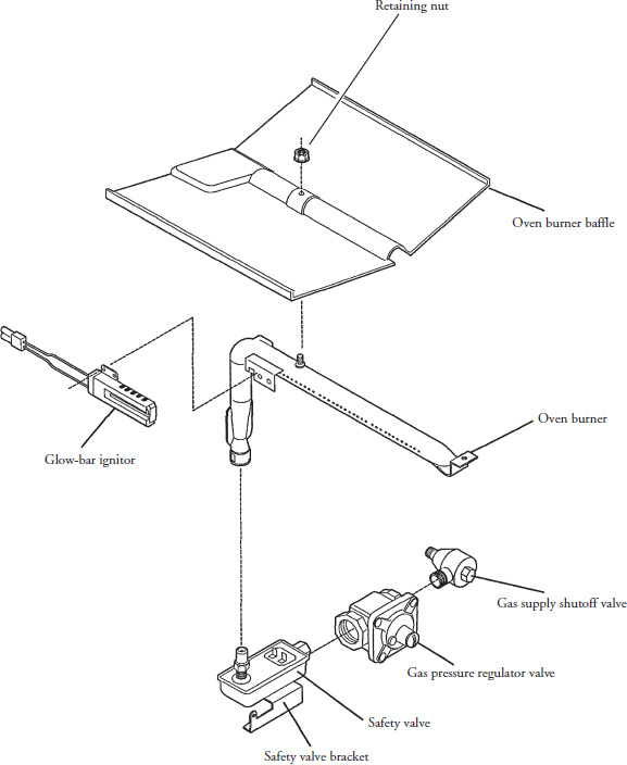
5. Gain access to the glow-bar ignitor. To gain access to the glow-bar ignitor (see Figures 23-11 and 23-13), open the oven door, remove the oven racks, and remove the oven floor panel. Next, remove the nut (Figure 23-19) from the oven burner baffle, and remove the baffle. You now have access to all of the components shown in Figure 23-19.
FIGURE 23-19 An exploded view of the components that make up the oven burner system.
6. Test the glow-bar ignitor. Disconnect the glow-bar ignitor wires from the wiring harness. Set your ohmmeter on the R x 100 scale, and check for continuity at the glow-bar ignitor wire terminals. Read the meter scale—at room temperature of 75 degrees F, the resistance of the glow-bar ignitor should between 50 and 1100 ohms. If it is under 50 or over 1200 ohms, replace the ignitor. If you are testing the glow-bar ignitor for amperage and it’s below 2.5 amps, replace it.
7. Remove the glow-bar ignitor. To remove the ignitor, remove the screws that secure the glow-bar ignitor to the oven burner (see Figures 23-11, 23-13, and 23-19).
8. Install the new glow-bar ignitor. To install the new glow-bar ignitor, just reverse the disassembly procedure, and reassemble. Be careful—do not touch the silicon carbide bar within the metal enclosure. If you do, it will create a hot spot on the silicon carbide bar (from body oils), and the ignitor might burn out. Turn on the electric and gas supply, and test the glow-bar ignitor. On electronic models, make sure to take the range/oven out of the service test mode when the repair is completed.
Pressure Regulator Valve
This mechanical device will perform two functions: it will reduce the higher incoming gas pressure to a desired lower pressure, and it will maintain a steady and an even flow of gas through the regulator valve. This valve is located in the bottom rear of the range or it can be located under the cooktop in the left or right rear.
The typical complaints associated with the pressure regulator valve are:
• The oven/broiler burner will not ignite. No gas is supplied to the burner.
• Erratic oven/broiler burner flame. The flame will fluctuate between high and low.
• Unusual display readouts and/or error codes.
To handle these problems, perform the following steps:
1. Verify the complaint. Verify the complaint by turning on the appliance. Do the surface burners come on? Are the burner flames small and blue in color? Did you check the gas pressure at the gas supply line, surface burners, and the oven burner? Do the burner flames fluctuate in size? Is the pilot light staying lit? Is there a gas smell near the pressure regulator valve? On electronic models, turn off the electricity to the appliance and wait for two minutes before turning it back on. If a fault code appears, look up the code. If the range/oven will not power up, locate the technical data sheet behind the control panel or for diagnostics information. On some models you will need the actual service manual for the model you are working on to properly diagnose the range/oven. The service manual will assist you in properly placing the range/oven in the service test mode for testing the range/oven functions.
2. Check for external factors. You must check for external factors not associated with the appliance. Is the appliance installed properly? Are there 120 volts to the appliance? The voltage at the receptacle is between 108 volts and 132 volts during a load on the circuit. Do you have the correct polarity? (See Chapter 6.) Is the gas to the appliance turned on?
3. Disconnect the electricity. Before working on the range or cooktop, disconnect the electricity to the appliance. This can be done by pulling the plug from the receptacle. Or disconnect the electricity at the fuse panel or at the circuit breaker panel. Turn off the electricity.
WARNING Some diagnostic tests will require you to test the components with the power turned on. When you disassemble the control panel, you can position it in such a way that the wiring will not make contact with metal. This act will allow you to test the components without electrical mishaps.
4. Shut off the gas supply. Before you begin servicing any gas components, shut off the supply of gas to the appliance. The shutoff valve should be within six feet of the gas appliance.
5. Gain access to the pressure regulator valve. Locate the pressure regulator valve. On some models, lift the cooktop or gain access through the oven cavity (see Figures 23-3, 23-11, 23-14, and 23-19).
6. Test the pressure regulator. The pressure regulator valve is a non-serviceable component. If you suspect a problem with the regulator, test the gas pressures with a manometer or a magnehelic gauge (see Figures 8-22 and 8-24). Test the gas pressure at the supply line before the pressure regulator valve and at the surface burner orifices. On some models using natural gas, the reading will be between a four- and six-inch water column. For LP models, the pressure will be between a nine- and eleven-inch water column. Next, test the gas pressure from the burner orifice and turn on all the burners; the pressure should remain constant. If the readings are not within the ranges mentioned, replace the pressure regulator.
7. Remove the gas pressure regulator valve. To remove the gas pressure valve (see Figure 23-14), pull out the range from the wall and lift up the cooktop. Disconnect the gas supply line from the range. Remove the gas line from the intake side of the regulator. Remove the surface burners, pull off the control knobs, and then remove the screws from the front panel (see Figure 23-14). This will expose the gas burner valves, thermostat, and manifold. Next, remove the thermostat from the manifold. If the model you are servicing has electronic ignition, remove the wires from the ignitor switches and label them. Finally, remove the screws that secure the manifold to the range. Figure 8-20 shows an exploded view of the gas components. Remove the manifold with the pressure regulator. Be careful—do not damage the capillary tube in the thermostat. To remove the gas pressure regulator valve (see Figures 23-11, 23-13, and 23-19), disconnect the gas line to the regulator. Remove the oven burner and ignitor. Next, remove the screws that secure the safety valve bracket to the range, and remove the safety valve with the regulator attached.
8. Install the new gas pressure regulator. To install the gas pressure regulator, just reverse the disassembly procedure, and reassemble. Make sure that you use approved pipe joint compound or yellow Teflon tape on the pipe connections (according to local codes) and on the threads of the pressure regulator valve before you install the valve in the range. Turn on the gas supply to the range. Check for gas leaks by using a chloride-free soap solution. Do not use a flame to check for gas leaks. The soap solution will begin to bubble if a leak is present. Turn on the electric and test the range operation. On electronic models , make sure to take the range/ oven out of the service test mode when the repair is completed.
Safety Valve
The safety valve is located in the bottom at the rear of the range or oven (Figures 23-5 and 23-11). The electric safety valve is wired in series with the ignitor or glow-bar. The safety valve will only open to allow gas to flow to the burner when there is enough current (2.5 to 4 amps) to cause the bimetal-controlled diaphragm within the valve body to warp open and allow the gas to flow through the safety valve to the burner.
The typical complaints associated with the safety valve are:
• The oven/broiler burner will not ignite. No gas is supplied to the burner.
• Broken capillary tube.
• Unusual display readouts and/or error codes.
To handle these problems, perform the following steps:
1. Verify the complaint. Verify the complaint by turning on the appliance. Does the oven or broil burner come on? On electronic models, turn off the electricity to the appliance and wait for two minutes before turning it back on. If a fault code appears, look up the code. If the range/oven will not power up, locate the technical data sheet behind the control panel or for diagnostics information. On some models you will need the actual service manual for the model you are working on to properly diagnose the range/oven. The service manual will assist you in properly placing the range/oven in the service test mode for testing the range/oven functions.
2. Check for external factors. You must check for external factors not associated with the appliance. Is the appliance installed properly? Are there 120 volts to the appliance? The voltage at the receptacle is between 108 volts and 132 volts during a load on the circuit. Do you have the correct polarity? (See Chapter 6.) Is the gas to the appliance turned on?
3. Disconnect the electricity. Before working on the range or cooktop, disconnect the electricity to the appliance. This can be done by pulling the plug from the receptacle. Or disconnect the electricity at the fuse panel or at the circuit breaker panel. Turn off the electricity.
WARNING Some diagnostic tests will require you to test the components with the power turned on. When you disassemble the control panel, you can position it in such a way that the wiring will not make contact with metal. This act will allow you to test the components without electrical mishaps.
4. Shut off the gas supply. Before you begin servicing any gas components, shut off the supply of gas to the appliance. The shutoff valve should be within six feet of the gas appliance.
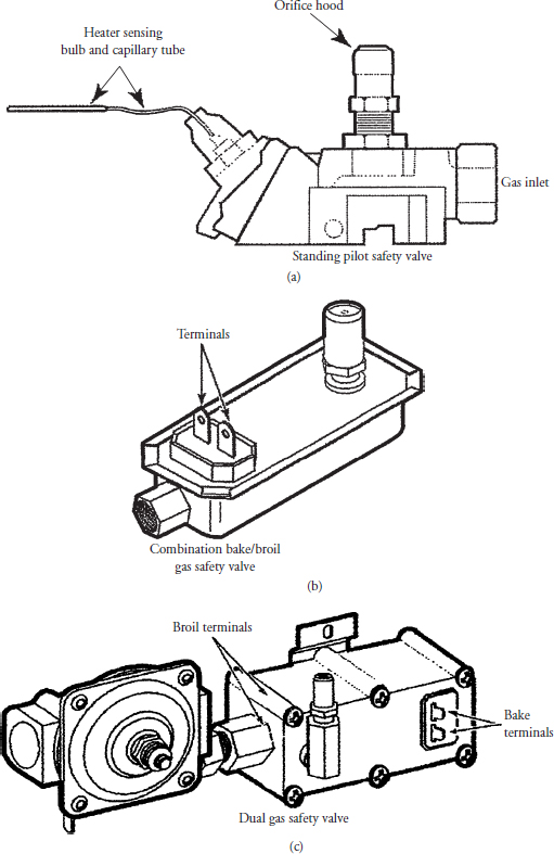
5. Gain access to the safety valve. To gain access to the safety valve (see Figure 23-20), open the oven door, remove the oven racks, and remove the oven floor panel. Next, remove the nut (see Figure 23-19) from the oven burner baffle, and remove the baffle. You now have access to all of the components shown in Figure 23-19.
FIGURE 23-20 (a) A standing pilot safety valve. (b) A combination bake/broil safety valve. (c) A dual gas safety valve with the pressure regulator attached.
6. Test the safety valve. The standing pilot safety valve cannot be tested: it is a temperature-controlled device. If you notice that the capillary tube is broken, replace the safety valve. Other models use an electrically controlled safety valve (bimetal operated). To test this type of valve (see Figure 23-20), set your ohmmeter to the R x 1 scale. Disconnect the wires from the valve terminals, and touch the ohmmeter probes to the terminals. The reading should be between 1 and 5 ohms. If your meter reads an open circuit or high resistance, the safety valve will have to be replaced.
7. Remove the safety valve. To remove the gas safety valve (see Figures 23-11, 23-13, and 23-19), disconnect the gas line to the regulator. Remove the oven burner and ignitor. Next, remove the screws that secure the safety valve bracket to the range, and remove the safety valve with the regulator attached.
8. Install the new safety valve. To install the safety valve, just reverse the disassembly procedure, and reassemble. Make sure that you use approved pipe joint compound or yellow Teflon tape on the pipe connections (according to local codes) and on the threads of the pressure regulator valve and the safety valve before you install the valve(s) in the range. Turn on the gas supply to the range. Check for gas leaks by using a chloride-free soap solution. Do not use a flame to check for gas leaks. The soap solution will begin to bubble if a leak is present. Turn on the electric and test the operation of the range/oven. On electronic models, make sure to take the range/ oven out of the service test mode when the repair is completed.
Electronic Control Board and User Interface Controls
The electronic control board and the user interface controls operate the bake, broil, time bake, and the self-clean functions of the range or oven. The electronic control board also displays the time of day, timer, and any error or fault codes. The electronic control board and the user interface controls are located in the control panel.
The typical complaints associated with the electronic control board or the user interface controls are:
• The range or oven won’t run or power up.
• Unable to program the range or oven.
• The display board will not display anything.
• One or more key pads will not accept commands.
• Unusual display readouts and/or error codes.
To prevent electrostatic discharge (ESD) from damaging expensive electronic components, follow the steps in Chapter 11.
To handle these problems, perform the following steps:
1. Verify the complaint. Verify the complaint by operating the range or oven. Turn off the electricity to the appliance and wait for two minutes before turning it back on. On electronic models, turn off the electricity to the appliance and wait for two minutes before turning it back on. If a fault code appears, look up the code. If the range/oven will not power up, locate the technical data sheet behind the control panel or for diagnostics information. On some models you will need the actual service manual for the model you are working on to properly diagnose the range/oven. The service manual will assist you in properly placing the range/oven in the service test mode for testing the range/oven functions.
2. Check for external factors. You must check for external factors not associated with the appliance. Are there 120 volts of electricity to the range or oven? The voltage at the receptacle is between 108 volts and 132 volts during a load on the circuit. Do you have the correct polarity? (See Chapter 6.)
3. Disconnect the electricity. Before working on the range or oven, disconnect the electricity. This can be done by pulling the plug out of the wall receptacle. Or disconnect the electricity at the fuse panel or circuit breaker panel. Turn off the electricity.
WARNING Some diagnostic tests will require you to test the components with the power turned on. When you disassemble the control panel, you can position the panel in such a way that the wiring will not make contact with metal. This will allow you to test the components without electrical mishaps.
4. Shut off the gas supply. Before you begin servicing any gas components, shut off the supply of gas to the appliance. The shutoff valve should be within six feet of the gas appliance.
5. Remove the console panel to gain access. You can access the electronic control board (some models have multiple circuit boards) by removing the back panel (see Figure 22-9) on a freestanding range. On models with front-mounted controls (see Figure 22-10), the panel is attached with screws on both ends. Remove the screws, and tilt the control panel. Be careful not to let the wires come off their components. Some built-in models have a removable backsplash (see Figure 22-11); just lift the backsplash and rest it on the cooktop. It would be a good idea to place something on the cooktop first to protect it from damage. Next, remove the screws from the backsplash that hold the rear panel to gain access to the electronic control board. If you are repairing a wall oven or an eye-level range, the control panel can be removed (see Figure 22-12) by opening the door and removing the screws that secure the panel. These might be underneath the front of the exhaust hood or just below the control panel. Some control panels are hinged; just tilt the control panel toward you for servicing. On other models, to gain access to the electronic control board, both the rear panel and the front control panel (usually glass) will have to be removed. Remove the screws that secure the trim piece that holds the glass in place.
6. Test the electronic control board and user interface control. If you are able to run the range/oven diagnostic test mode, check the different functions. Use the technical data sheet for the model you are servicing to locate the test points on the wiring schematic. Check all wiring connections and wiring. Using the technical data sheet, test the electronic control or user interface controls, input voltages, and output voltages. On some models, fuses are soldered to the printed circuit board (PCB). These fuses must be tested first before condemning the component.
7. Remove the electronic control board or user interface control. To remove the defective component, remove the screws that secure the boards to the control panel or range/oven frame. Disconnect the connectors from the electronic control board or user interface control.
8. Install the new component. To install a new electronic control board or user interface control, read the part installation literature that came with the part and just reverse the disassembly procedure, and reassemble. Reinstall the console panel, and restore the electricity and gas supply to the range/oven. Test the range/oven operation. On electronic models, make sure to take the range/oven out of the service test mode when the repair is completed.
Oven Temperature Sensor
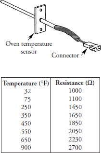
The oven temperature sensor (Figure 22-36) is a thermistor. The thermistor is a thermally sensitive resistor that exhibits a change in electrical resistance with a change in its temperature. The oven temperature sensor is located in the upper left or right attached to the rear wall of the oven cavity. The oven temperature sensor sends the resistance readings to the electronic oven control board. The electronic control board monitors the resistance readings of the oven temperature sensor and turns the bake or broil on or off at the desired temperature.
The typical complaints associated with the oven temperature sensor are:
• Erratic temperature in the oven cavity.
• The oven/broiler burner will not ignite.
• Unusual display readouts and/or error codes.
To handle these problems, perform the following steps:
1. Verify the complaint. Verify the complaint by turning on the appliance. Does the oven operate? Test the oven temperature. On electronic models, turn off the electricity to the appliance and wait for two minutes before turning it back on. If a fault code appears, look up the code. If the range/oven will not power up, locate the technical data sheet behind the control panel or for diagnostics information. On some models you will need the actual service manual for the model you are working on to properly diagnose the range/oven. The service manual will assist you in properly placing the range/ oven in the service test mode for testing the range/oven functions.
2. Check for external factors. You must check for external factors not associated with the appliance. Is the appliance installed properly? Are there 120 volts to the appliance? The voltage at the receptacle is between 108 volts and 132 volts during a load on the circuit. Do you have the correct polarity? (See Chapter 6.) Is the gas to the appliance turned on?
3. Disconnect the electricity. Before working on the range or cooktop, disconnect the electricity to the appliance. This can be done by pulling the plug from the receptacle. Or disconnect the electricity at the fuse panel or at the circuit breaker panel. Turn off the electricity.
WARNING Some diagnostic tests will require you to test the components with the power turned on. When you disassemble the control panel, you can position it in such a way that the wiring will not make contact with metal. This act will allow you to test the components without electrical mishaps.
4. Shut off the gas supply. Before you begin servicing any gas components, shut off the supply of gas to the appliance. The shutoff valve should be within six feet of the gas appliance.
5. Gain access to the oven temperature sensor. To gain access, open the oven door. The temperature sensor is located in the upper corners of the oven cavity.
6. Remove the oven temperature sensor. Remove the oven racks. Remove the two screws that secure the sensor to the oven cavity wall. Pull the sensor toward you gently, disconnect the connector, and remove the temperature sensor from the oven. There may be times when the connector will not pass through the hole in the oven cavity. If this is the case, then you will have to access the connector from the rear of the range/oven. On some models, to access the temperature sensor, you will have to remove the temperature sensor from the rear of the range/oven by removing the screws that secure the sensor to the oven cavity in the rear of the range/oven.
7. Test the oven temperature sensor. Set your ohmmeter on the R × 10 scale, and measure the resistance between the two pin connectors on the sensor wire connector. For most sensors, the meter reading at room temperature should match the chart in Figure 23-21. For example: If the room temperature is approximately 75 degrees Fahrenheit, the resistance in the sensor will be 1100 ohms. If the reading is less than 1000 ohms, replace the sensor. If the reading is above 1100 ohms at 75 degrees, replace the sensor.
FIGURE 23-21 A typical oven temperature sensor. This type of sensor is only used in ranges and ovens with electronic controls.
8. Install the new oven temperature sensor. To install the oven temperature sensor, just reverse the disassembly procedure, and reassemble. Turn on the electric and the gas supply and test the oven temperature. On electronic models, make sure to take the range/oven out of the service test mode when the repair is completed. With an oven temperature tester, place the thermocouple tip in the center of the oven cavity. Be sure that the thermocouple tip does not touch any metal. Close the oven door, set the oven to bake, and adjust the thermostat setting to the 350-degree mark. Let the oven cycle for 20 to 30 minutes. Then record the minimum and maximum temperatures of three cycles. Next, add these temperatures, and divide by 6. This will give you the average temperature of the oven:
The average temperature calculated should be within ±5 degrees of the temperature setting selected. Oven temperature sensors (RTDs) are used with electronically controlled ovens. To make any temperature adjustments in the electronic control, the technician needs to locate the technical data sheet. This sheet will show you how to make the temperature adjustments for the model you are servicing.
Thermostat (Standing Pilot)
The oven thermostat is located in the control panel and it is mounted on the manifold pipe. The thermostat is a hydraulic valve that has two separate gas lines and a sensing bulb (Figure 23-5). The pilot gas line maintains a pilot flame in the oven, and the main gas line provides gas to the safety gas valve. The sensing bulb is a mercury-filled tube attached to a capillary tube that controls the thermostat to open or close the gas supply to the oven burner. The thermostat operates on temperature change it senses from within the oven cavity. The typical complaints associated with the thermostat are:
• The oven/broiler burner will not come on.
• Erratic oven cavity temperatures.
To handle these problems, perform the following steps:
1. Verify the complaint. Verify the complaint by turning on the appliance. Does the oven operate? Test the oven temperature.
2. Check for external factors. You must check for external factors not associated with the appliance. Is the appliance installed properly? Are there 120 volts to the appliance? The voltage at the receptacle is between 108 volts and 132 volts during a load on the circuit. Do you have the correct polarity? (See Chapter 6.) Is the gas to the appliance turned on?
3. Disconnect the electricity. Before working on the range or cooktop, disconnect the electricity to the appliance. This can be done by pulling the plug from the receptacle. Or disconnect the electricity at the fuse panel or at the circuit breaker panel. Turn off the electricity.
WARNING Some diagnostic tests will require you to test the components with the power turned on. When you disassemble the control panel, you can position it in such a way that the wiring will not make contact with metal. This act will allow you to test the components without electrical mishaps.
4. Shut off the gas supply. Before you begin servicing any gas components, shut off the supply of gas to the appliance. The shutoff valve should be within six feet of the gas appliance.
5. Gain access to the oven thermostat. To gain access to the oven thermostat, lift up the cooktop, pull off the control knobs, and then remove the screws from the front panel (see Figure 23-14). Remove the control panel. This will expose the gas burner valves, thermostat, and manifold (see Figures 8-20 and 23-5).
6. Remove the thermostat. Before removing the thermostat, remove the capillary tube and sensor from the oven cavity. The sensing bulb will be attached by two retaining clips. Squeeze the clips, pull away from the oven cavity, and remove the sensing bulb and capillary tubing. Feed the capillary tubing through the oven cavity to the top of the range. Disconnect the main gas line and the pilot gas line from the thermostat. Then remove the screws that secure the thermostat to the manifold (see Figures 8-20 and 23-5).
7. Install the new thermostat. To install the thermostat, just reverse the disassembly procedure, and reassemble. Make sure that you use approved pipe joint compound or yellow Teflon tape on the pipe connections (according to local codes) and on the threads of the gas lines (if needed) before you install the thermostat on the manifold. Turn on the gas supply to the range. Check for gas leaks by using a chloride-free soap solution. Do not use a flame to check for gas leaks. The soap solution will begin to bubble if a leak is present.
8. Test the oven temperature. Turn on the electric and gas supply to the range/oven. With an oven temperature tester, place the thermocouple tip in the center of the oven cavity. Be sure that the thermocouple tip does not touch any metal. Close the oven door, set the oven to bake, and adjust the thermostat setting to the 350-degree mark. Let the oven cycle for 20 to 30 minutes. Then record the minimum and maximum temperatures of three cycles. Next, add these temperatures, and divide by 6. This will give you the average temperature of the oven:
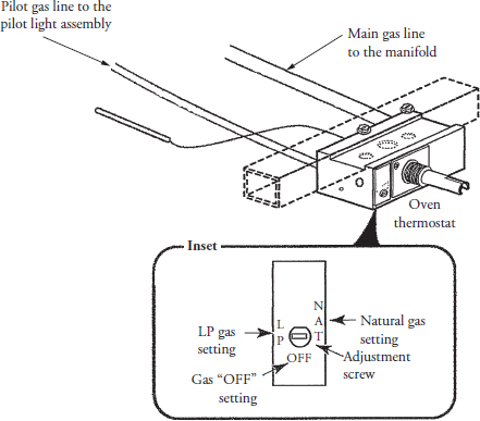
The average temperature calculated should be within ±25 degrees of the temperature setting selected. If not, try calibrating the thermostat. To calibrate the thermostat, pull the oven thermostat knob off, and look at the thermostat (see inset in Figure 23-22). The slotted screw on the thermostat is for converting the thermostat for the type of gas supplied to the range. Set it to the proper setting. If you look into the thermostat stem, you will see a small adjustment screw. This screw is used for calibrating the thermostat. Turning the screw slightly to the right will increase the temperature. To decrease the temperature setting, turn the screw to the left slightly. For every adjustment made, you must test the oven temperature as stated above.
FIGURE 23-22 When converting the range to the type of gas that is supplied to the home, you must convert the thermostat as well.
Range/Oven Time Clock
The range/oven time clock is located in the control panel. The clock runs on 120 volts and controls the timer, time bake, clean cycle, and shows the time of day. On electronic models the clock will display error/ fault codes also.
The typical complaints associated with failure of the range/oven time clock are:
• Timed bake cycle will not operate.
• Unable to use the self-cleaning cycle.
• Clock loses time.
• Clock is not functioning.
• The minute reminder is not functioning.
• Unusual display readouts and/or error codes.
To handle these problems, perform the following steps:
1. Verify the complaint. Verify the complaint by turning the clock controls to the correct time. Does the clock time advance? Some models have the minute reminder located on the same clock. Set this timer to test it. Does it advance? Turn off the electricity to the appliance and wait for two minutes before turning it back on. If a fault code appears, look up the code. If the range/oven will not power up, locate the technical data sheet behind the control panel for the diagnostics information. On some models you will need the actual service manual for the model you are working on to properly diagnose the range/oven. The service manual will assist you in properly placing the range/oven in the service test mode for testing the range/oven functions.
2. Check for external factors. You must check for external factors not associated with the appliance. Is the fuse blown? Does the appliance have the correct voltage? The voltage at the receptacle is between 198 volts and 264 volts during a load on the circuit (see Chapter 6).
3. Disconnect the electricity. Before working on the range or oven, disconnect the electricity to the appliance. This can be done by pulling the plug from the receptacle. Or disconnect the electricity at the fuse panel or at the circuit breaker panel. Turn off the electricity.
WARNING Some diagnostic tests will require you to test the components with the power turned on. When you disassemble the control panel, you can position it in such a way that the wiring will not make contact with metal. This act will allow you to test the components without electrical mishaps.
4. Gain access to the range/oven clock. You can access the clock by removing the back panel (see Figure 22-9) on a freestanding range. On models with front-mounted controls (see Figure 22-10), the panel is attached with screws on both ends. Remove the screws, and tilt the control panel. Be careful not to let the wires come off their components. Some built-in models have a removable backsplash (see Figure 22-11); just lift the backsplash and rest it on the cooktop. It would be a good idea to place something on the cooktop first to protect it from damage. Next, remove the screws from the backsplash that hold the rear panel to gain access to the clock. If you are repairing a wall oven or an eye-level range, the control panel can be removed (see Figure 22-12) by opening the door and removing the screws that secure the panel. These might be underneath the front of the exhaust hood or just below the control panel. Some control panels are hinged; just tilt the control panel toward you for servicing. On other models, to gain access to the clock, both the rear panel and the front control panel (usually glass) will have to be removed. Remove the screws that secure the trim piece that holds the glass in place. Then remove the trim piece. On some models, the trim might have to be removed first. Figure 22-40 illustrates the different types of clock faces available on ranges/ovens.
5. Test the range/oven clock. On some models, if the clock does not run, check for a fuse in the circuit. Locate the clock motor wire leads, and isolate them from the circuit (label them). Using the ohmmeter, set the range scale on R x 1. Place the probes on the clock motor leads; there should be continuity. If not, replace the clock. On some models, the clock is used to control the timed baking and the self-cleaning cycles (see Figures 22-40b, 22-40c, and 22-40d). To check the switch mechanism of the clock, remove the wires from the switch terminals (label them). Using the ohmmeter, set the range scale on R x 1. Place the probes on the terminals. Look at the wiring diagram for the correct terminals to test. Some models have one switch; other models have two sets of switches. Test for continuity of the switch contacts when you push in and turn the start and stop knobs on the clock and when the knobs pop out. On electronic control models, refer to the technical data sheet located in the range for the testing procedure.
6. Remove the range/oven time clock. First remove the clock knobs from the stems. To remove the range/oven time clock in this model (Figure 22-41), use a screwdriver and depress the clips that hold the clock to the control panel. On other models, the clock is secured to the control panel by screws or nuts. Pull the clock toward the front of the appliance (Figure 22-42).
7. Install a new range/oven clock. Transfer the wires from the old clock to the new clock. Be sure that you install the wires on their correct terminals according to the wiring diagram. To install the new range/oven clock, just reverse the disassembly procedure and reassemble. Turn on the electric and gas supply and test the operation of the product.
Flame Adjustments
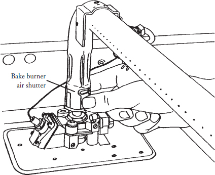
There may be times when the surface, oven, or broil burner flame needs to be adjusted. The proper surface burner flame should be about 5/8 inch high with a well-defined blue flame. If the gas pressure to the burner is correct, all you have to do is adjust the air shutter on the surface burner (see Figure 23-16) to obtain the correct size and color. The oven and broil burners’ flame should be about 3/4 inch high with a well-defined blue flame. With the correct gas pressure to the burners, all that is needed is to adjust the air shutters on the burners (Figures 23-13 and 23-23) to obtain the correct size and color. For sealed burner cooktops, you cannot make any air adjustments.
FIGURE 23-23 Adjusting the air shutter on the oven burner.
Diagnostic Charts and Wiring Diagrams
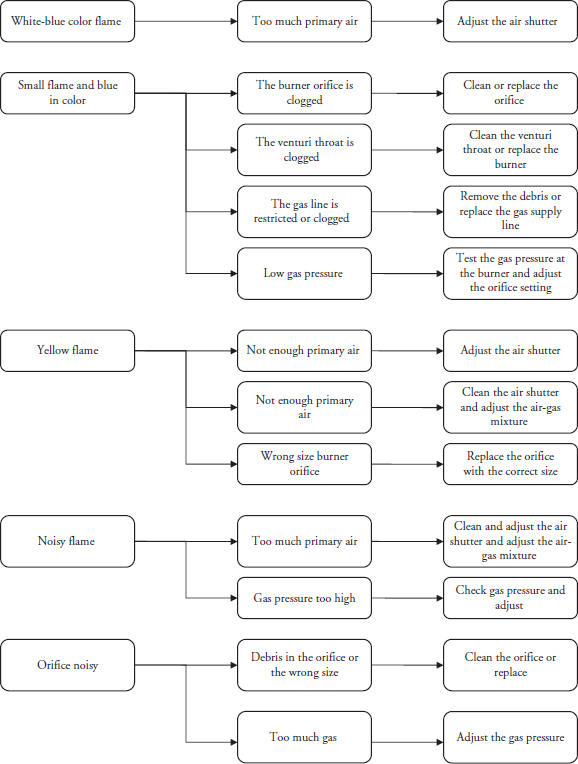
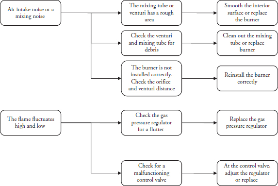
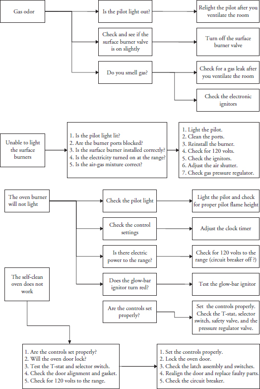
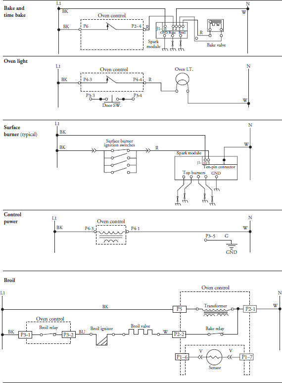
The following diagnostic flowcharts will help you to pinpoint the likely causes of the various problems associated with gas ranges and ovens (Figures 23-24 and 23-25). The wiring diagrams in this chapter are examples only. You must refer to the actual wiring diagram for the range, oven, or cooktop that you are servicing. Figure 23-26 depicts samples of actual strip circuit diagrams. The strip circuit diagram is simpler and is usually easier to read. Figures 23-18 and 23-27 depict actual wiring schematic diagrams.
FIGURE 23-24 Flowchart identifying the causes of various flame characteristics.
FIGURE 23-25 Diagnostic flowchart: gas odor; unable to light the surface burners; the oven burner will not light; the self-cleaning feature does not work.
FIGURE 23-26 The strip circuit diagram is easy to read and understand.
FIGURE 23-27 A typical wiring schematic for a self-cleaning range with electronic controls.
