Chapter 14
Cisco DNA Automation
As outlined in Chapter 13, “Device Programmability,” device programmability lays the foundation for more sophisticated network automation. Device programmability allows you to interact with physical and virtual network elements using a machine-to-machine paradigm in a predictable and deterministic manner. The desired functionality is automated into the network layer using APIs. Cisco DNA automation, however, goes well beyond network element automation via the device level. It allows you to treat your network “as a system” in itself, to operate on multiple network elements simultaneously with consistency. Network controllers play a crucial role in Cisco DNA, providing capabilities to standardize configuration and common network settings and drive these into the infrastructure using device programmability. Controllers also allow for the creation and maintenance of a detailed device inventory of your network that once created can offer a visualization of the network topology. Controllers also enable operators to carry out management functions on multiple network devices at the same time with consistency.
This chapter discusses the importance of Cisco DNA automation as a major functional block in the architecture. The following section reviews the need for sophisticated automation functions in general—whether automating device-by-device operations or using network controllers. The section highlights the business benefits at a high level. It then examines some impediments to automation. What stops network operators from increasing the level of automation? A large part of this chapter is devoted to the automation capabilities that are offered by a network controller. It emphasizes the difference between device-by-device automation and network-controller automation, exploring the different stages of Cisco DNA automation in subsequent sections.
This chapter explains the following:
Standardizing network designs
Automating the deployment and configuration of network functions
Ongoing lifecycle management of the Cisco DNA network elements
This chapter finishes with a deep dive into the functional architecture for automation in Cisco DNA, in particular the role of a network controller for automation.
The Increasing Importance of Automation
Automating network operations is not new. Anybody starting to learn the capabilities of routers, switches, access points, or other networking elements in a lab or training course is traditionally exposed to configuring features using the command-line interface (CLI). Students quickly realize the shortcomings of this approach. You mistype a command but get insufficient feedback on what the proper syntax should be. You enter a valid syntax for a command but misinterpret its behavior and do not obtain the desired functionality. And to understand and verify the operation of the network element, you again issue CLI-based commands to show its state, and are returned sometimes multiple screen-lengths of data that you subsequently have to scan and interpret to find the statistic that you were looking for.
Imagine then that you are an operator of even a small network with a few routers, switches, wireless access points, and firewalls. The manual and cumbersome process that you tried in the lab now has to be repeated for all the different types of network elements (routers, switches, wireless access points, firewalls, IPS/IDS, WAN optimization, deep-packet inspection appliances, etc.). A multivendor environment often further complicates the operational procedures because every vendor has its own operational models for its systems. And for larger networks, such a manual, CLI-based approach is simply not sustainable.
The benefits of using automated network operations have thus been apparent for a long time for any operator of even small networks. Mechanisms such as standardizing a configuration for a particular device type, automating the deployment of the standardized configurations into the network devices and status verification, and even automating the extraction of relevant data points from the show commands have been common practices for many years. Some operators use network management tools to assist in the task of network automation. Others rely more on self-developed scripts to accommodate unique automation scenarios. Combinations of tool-based and scripted automations are common in many operational networks.
The recent trends in networking in a digitalized world described in Chapter 4, “Introducing the Cisco Digital Network Architecture,” motivate a heightened interest in sophisticated automation functions. The principal underlying driver for this evolution is cost reduction. Automating network operations procedures promises in particular the potential to keep operational expenditures (OPEX) in line as architectures evolve to support digitalized business processes. The benefits of automation in Cisco DNA are viewed from several aspects, which include the following:
Allow the network to scale
Reduce errors in the network
Time to perform an operation
Security and compliance
Allow the Network to Scale
Cisco DNA is designed to scale to accommodate an ever-increasing number of endpoints. Individual users increasingly attach to the network with multiple devices at the same time. More and more Internet of Things (IoT) devices are also deployed and need to be networked, with a wide variety of requirements on the network. Some IoT endpoints are geographically co-located with users, but generate and consume high-bandwidth streams. At the other end of the spectrum are highly distributed sensors, deployed in huge numbers but each generating small amounts of traffic.
The growth in endpoints typically needs to be complemented by a growth in the network infrastructure. More access points and switches are needed to connect the endpoints to the network, which in turn triggers increases at the various aggregation layers. Also, supporting network functions such as firewalls, IPS/IDS, or unified threat management (UTM) systems is likely required in larger numbers to meet these demands. Automating the deployment, configuration, and ongoing operations of the network is crucial in this environment to allow the number of endpoints to scale.
Reduce Errors in the Network
One of the main advantages of automation is to introduce predictability and determinism. By its very definition, automation is “the controlled operation of an apparatus, process, or system by mechanical or electronic devices that take the place of human labor.”1 If you have an automation script to drive a predetermined configuration into a router, say, the execution of the script must always yield the same result. Under the assumption that the initial state of the target network element is well known and stable, and that the automation procedure was tested and validated, its execution should always produce the same target end state.
1 https://www.merriam-webster.com/dictionary/automation
Automation helps reduce the errors in network configurations that are often incurred by manual operations. The execution of an automation script should bring about the same end result every time. Ideally, automation also helps bring the entire network into a well-known state, where the configuration and operational status of each network device is deterministic at any point in time. And this helps reduce operational expenses: once the automation procedure is validated, you spend less time troubleshooting and correcting configuration errors. And the same procedure can be applied across many network elements at the same time, rather than executing a sequential manual process that may break in different ways each time a manual operation is executed.
Time to Perform an Operation
Many systems are measured also in “time to X.” Your network operations team may be measured by the time taken to deploy a new network element. IT operators may be measured by the time taken to onboard a new user. Similarly, the network support team may be measured by the time to troubleshoot and resolve a misconfiguration. One of the key benefits of automation is the ability to reduce the time it takes to perform an operation. Imagine you have a graphical operations environment (such as Cisco DNA Center) that allows you to upload a new configuration to enable a new service (e.g., a new security function) in the network. You provide the configuration snipped as part of the design phase, select the domains and devices where this new capability should be deployed, and click a button. An automated procedure is able to leverage machine-to-machine communications to drive the functionality into the desired network element within minutes. Ideally, the automation also reports on the outcome to confirm the successful execution of the operation, or to flag any unforeseen conditions that prevented the operation from succeeding.
One of the key benefits of automation is to reduce the time to execute an operation. This enables you to deploy new Cisco DNA services for end users or new network functions much faster. It also allows you to reduce the time to troubleshoot issues, leading to a greater operator and user experience.
Security and Compliance
Automation also has significant benefits to meet the security and compliance needs required in a digitalized network. As the network becomes increasingly vital for digitalized business processes, it is a prime target for security attacks. Recent reports of attacks, such as the malicious lockout of hotel guests from their rooms at a ski resort highlight the vulnerability of many networks and the negative business impact caused. Controller-based automation in particular not only helps to detect an attack using various mechanisms (e.g., anomaly detection), but also installs remedies to a particular attack throughout the entire network almost immediately after the safeguard was devised.
Automating security operations does not apply only to special events such as an attack. It should be leveraged to comply with internal or regulatory compliance procedures. A network controller can automate the instantiation of configurations that were approved by your compliance team, run audit checks to verify that these configurations are effective, and offer proof of compliance by logging all events.
Current Impediments to Automation
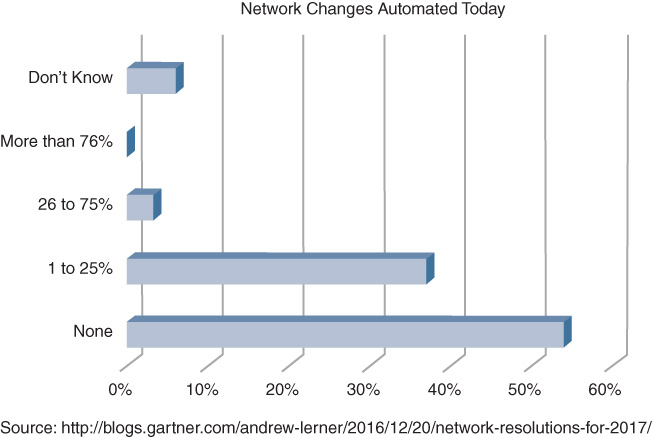
Despite the apparent benefits of automation discussed in the previous section, many enterprises still face obstacles to fully automate their network and security operations. A study by Gartner reported on the percentage of network changes that are automated in today’s enterprise networks. Over 50 percent of enterprises still do not automate network changes, and 37 percent of all respondents automate up to 25 percent of all changes. According to a Gartner Blog Network blog entry referencing this study2 and as illustrated in Figure 14-1, “Multiple surveys and client interactions indicate that 80+% of network changes are manually driven.” Note that these data points do not distinguish between device-level automation and controller-based automation. The results report on the state of automation for network changes in general, and highlight the significant potential that any level of automation can still offer.
2 Andrew Lerner, “Network Resolutions for 2017,” Gartner Blog, Dec. 20, 2016, https://blogs.gartner.com/andrew-lerner/2016/12/20/network-resolutions-for-2017/
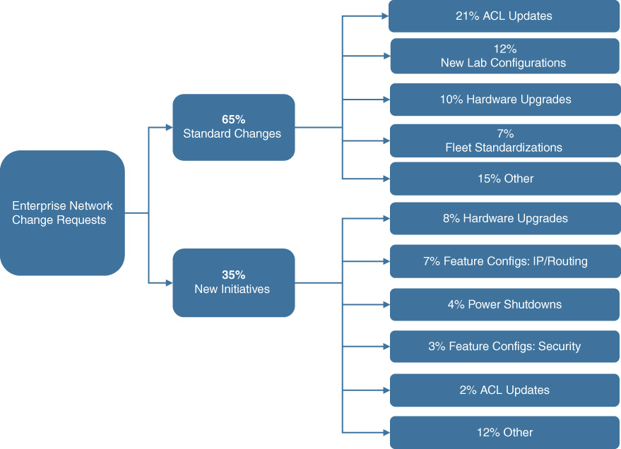
A recent internal study by Cisco complements these findings by Gartner. The study analyzed over 1500 cases for network changes and categorized these into standard and nonstandard changes. Standard changes were defined to be those that have well-defined procedures and workflows, that are repetitive, and thus are prime candidates to be automated. Examples of cases in this category are access control list (ACL) updates, hardware upgrades, standardizing deployments to corporate specifications, or even configuring laboratory environments with well-known connectivity parameters. Of the 1500 cases analyzed, about 65 percent of all changes fell into this category.
The remaining 35 percent of cases were classified to be nonstandard, defined to require procedures and workflows that were not encountered before, or where a highly skilled network engineer is required for the solution. Some of the hardware upgrade cases were associated with this category. Other examples include special routing configurations, security or ACL changes, or dealing with power shutdowns. Figure 14-2 provides the detailed categorization of the analyzed cases.
So what is stopping many enterprises from increasing the level of automation in their networks? In addition to the mentioned finding that not all operations and changes can be automated, there are often historical and organizational reasons for the lack of automation.
First on the list of obstacles are “snowflakes.” Many networks have evolved over time, resulting in a wide variety of network element generations and architectures that are operated concurrently. Technologies introduced years ago may still be operated to save costs. Depreciated assets continue to run where possible to delay replacement costs. At the same time, newer network elements are introduced to satisfy new demands for connectivity, or to fulfill growth when the existing network element types can no longer be purchased due to vendor end-of-sale lifecycles.
Mergers and acquisitions are another reason resulting in a highly diverse networking landscape. The networks from different companies that are merging are likely very different. Building a coherent standardized network architecture after a merger or acquisition can be very hard and disruptive, so different networks based on multiple vendors are allowed to coexist. As enterprises evolve, so do their networks, and the results are often snowflakes—none of which are alike—where in the extreme many disparate networks coexist, with network elements that all seem to have individual configurations. Automating snowflakes is impossible, because automation assumes that the same procedure or configuration is applied multiple times. Standardizing on network operations, procedures, configurations, and hardware elements is thus a fundamental requirement to benefit from automation.
Second, organizational structures often also inhibit automation and standardization. In some enterprises, individual departments operate their own network infrastructures. For example, manufacturing may have its own network, separate from the sales and finance departments. For global enterprises, the network in Asia and Europe may be architected and run separate from the Americas network. Large enterprises may thus have multiple networking departments aligning to the organizational structure. And each network department is likely implementing different operational procedures, with possibly different suppliers for networking equipment than the other, resulting in multiple ‘standards’ even within the same enterprise.
Third on the obstacles list is employee behavior. For some employees, automation is perceived as a threat to their job. Many directors of IT and networking departments encounter resistance of their staff to automate. Statements such as “I am concerned that automation will put me out of a job” or “If I automate my job, I will become redundant in the organization” are not uncommon sentiments by many IT employees. As a result, many an automation project may not progress as planned or succeed.
Last, some enterprises may not choose to standardize, especially when a multivendor environment is desired by corporate policy. Full standardization may be hard to achieve in such an environment. Normalizing the set of functions deployed in your network among multiple vendors often takes more time, as vendors support functionality at a different development pace. Full standardization may sometimes come at the cost of deployment flexibility and speed of innovation in such environments.
None of these obstacles are insurmountable! Standard network architectures and procedures can be enforced. Concerns by IT staff can be addressed by demonstrations that the individuals become more productive for the organization through automation, rather than being replaced by automation. They are able to do more with less. But you have to be aware that such concerns exists and are real, and address them appropriately if you want to successfully automate your network operations.
Classifying Network Automation Tasks
The problem of automating network operations can be dissected from several angles. The target network operations can be subclassified into those that touch the network infrastructure and those that touch the clients of the network (users, devices, or applications). Automation operations can also be classified into standard and nonstandard changes. In the former category are mainly routine operations that are repetitive in nature. The latter class of changes may be more sophisticated, requiring networking experts and more elaborate workflows to complete. This section elaborates on these classifications to deepen your understanding of network automation.
Infrastructure and Cisco DNA Service Automation
In a Cisco Digitalized Network Architecture, automation is categorized into two main sets of activities:
Systematically configuring the network infrastructure (such as routers, switches, access points, and auxiliary network functions)
Provisioning Cisco DNA services connecting users, devices, and applications with each other, leveraging software interactions between a network controller and the network infrastructure
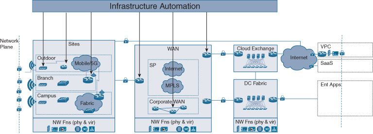
Automated configuration of the network infrastructure focuses on getting the network up and running. Network elements must be deployed and configured to form a network architecture, rather than remain a disjointed set of physical boxes or virtual machines. Examples of infrastructure automation are the programmatic deployment of a virtual router, or the configuration of the routing algorithms in all the switches and routers forming a software-defined access network.
Once the architecture is set up, it also must be maintained to continue to operate. Configurations may need to be updated, software images may need to be upgraded, and licenses for network software may need to be renewed. All of these operations center on the network infrastructure, rather than providing a transport service that is exposed to and consumed by endpoints that connect to the network. The concept of Cisco DNA infrastructure automation is illustrated in Figure 14-3.
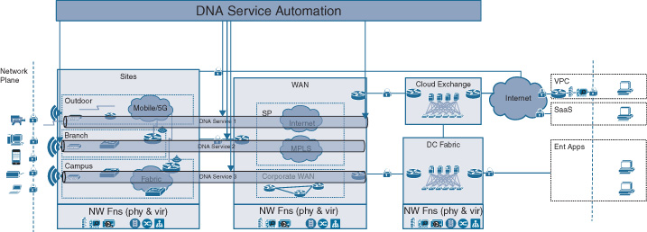
The second set of automation activities are those that allow endpoints—users, applications, or devices—to use the network for their communication requirements. New users must be authorized to consume Cisco DNA network services. Devices and applications may need to be segmented to implement security policies. You may have received an alarm about a malicious user or an unusual traffic pattern and consequently forced traffic from the suspected origin to be redirected for further analysis. All of these are examples of processes touching endpoints, where the network infrastructure is consumed to transport IP traffic from a source to a destination. In many cases, these activities often have an element of policy associated with them. Access policies are automated to grant or deny access to a user, device, or application. Access control policies or application policies are instrumented to automatically regulate the communication between endpoint groups or the treatment of specific application flows, respectively. The concept of Cisco DNA service automation is illustrated in Figure 14-4.
Standard and Nonstandard Automation Tasks
Cisco DNA infrastructure automation revolves around the everyday tasks for many network operations teams: performing standard or nonstandard changes to keep the network infrastructure up and running.
Standard changes are defined as those that are repetitive, require no approvals, and typically have minimal or no disruption to network operations. They are often mundane in nature. Examples of standard network changes are
Deploying and managing auxiliary network functions, such as
DHCP/DNS servers
NTP servers
Syslog servers
NetFlow collectors
Configuring and managing authentication, authorization, and accounting (AAA) for the network infrastructure elements, including some Secure Shell (SSH)/Telnet or Simple Network Management Protocol (SNMP) configurations, or their password management
In contrast, nonstandard changes typically are more disruptive to network operations, often requiring approvals from senior architects or experts. They also often require cooperation of multiple operations teams to implement, such as the data center team or the security operations teams. Nonstandard changes often have a device-specific aspect, differing for routers, switches, or wireless LAN controllers (WLC). Table 14-1 lists some examples of nonstandard network changes by device type.
Table 14-1 Examples of Nonstandard Network Infrastructure Changes
Routers |
Switches |
WLCs |
Interface configurations |
Interface configurations |
Service set identifier (SSID) |
ACLs |
Spanning tree |
Radio frequency (RF) configurations |
Voice dial plans |
Virtual local area networks (VLAN) |
Security/crypto |
Virtual routing and forwarding (VRF) configurations |
Security/crypto |
QoS |
Routing protocols |
QoS |
Deep packet inspection |
Tunnel configuration |
Deep packet inspection |
|
Security/crypto |
|
|
Quality of service (QoS) |
|
|
Deep packet inspection |
|
|
Both standard and nonstandard operations benefit from automation. Standard network changes are low-hanging fruit for automation. They are typically common across the different types of network element, needing to be operated on routers, switches, wireless LAN controllers, etc. Nonstandard changes, on the other hand, may require more elaborate support from the automation environment. For example, a flexible notion of a workflow process can help with a chain of approvals that is often required in nonstandard changes, or allow different experts in your team to perform parts of the automated nonstandard changes.
Figure 14-5 illustrates an example of such a workflow, designed to help a network architect to design a new virtualized enterprise branch topology template. To create a new branch template, you have to be aware of the overall geographic network hierarchy consisting of sites, buildings, and floors. From a networking perspective, IP pools are associated with network elements in the sites, becoming an attribute of the site profile. Other attributes could be the list of certified images to be deployed in the network elements of that site, or the characteristics of the WAN connectivity that is typically contracted out to a service provider. The site template also characterizes the types of network elements to be deployed, as well as their prescribed configurations.
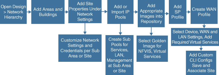
The later section “Automating Your Network with Cisco DNA Center” elaborates on such automated workflows.
The Role of Controllers in Cisco DNA Automation
Chapter 5, “The Cisco Digital Network Architecture Blueprint,” introduced the concept of network controllers as an architectural building block. Network controllers become an essential component for automation. They allow you to operate on the network as a system in itself.
Imagine your network as a loosely coupled collection of network elements of different types. Today, many enterprise operators manipulate such individual network elements. To enable Layer 3 reachability in the WAN, routing configurations are pushed into routers one system at a time. Similarly, to establish Layer 2 connectivity in the campus, switches are configured with the appropriate VLAN, spanning tree, or security functions.
But element-by-element operations do not guarantee that the desired end-to-end behavior is successful. A single misconfiguration of a router can potentially break end-to-end reachability. A wrongly applied bridge priority can have detrimental effects on the switching topology. Even if automation is applied on a device-by-device basis, device-specific configurations have to be taken into account. Every network device likely has its own specific parameters such as device IP addresses, or possibly different QoS configurations that are a function of the device’s place in the network. Such device-specific parameters are often a cause of error in manual or automated device-by-device configurations. The network remains a loosely coupled set of individual network elements, rather than a coherent system on its own.
The benefit of the controllers in Cisco DNA is to provide a domain-wide view of your network architecture and to operate on it coherently as a system. The controller allows network architects to standardize the network topology for the constituent sites and for the network domain under the controller’s governance. For network operators, the controller enables the execution of configuration changes consistently throughout the network, ensuring that the integrity and cohesiveness of the network is maintained. It is this domain-wide view of your network architecture that makes the Cisco DNA controller an invaluable element in the architecture to
Create the transport and network functions infrastructure
Maintain a view of the infrastructure functions and connected endpoints
Instantiate and maintain Cisco DNA services
Leveraging Abstractions in Cisco DNA to Deliver Intent-Based Networking
Another main advantage of the controller for automation is the introduction of an abstraction layer for network operations. By governing a particular network domain as a system, you can describe the intended behavior in a more abstract, network-wide manner, instead of specifying a set of very detailed configuration commands requiring sophisticated parameter details. Higher-level expressions of network behavior are the fundamental building blocks of intent-based networking (IBN), which aims to put the spotlight of network operations on describing the desired behavior using abstractions.
Consider for example that you as a network operator want to prioritize an application. Current network operations focus on automating the instructions on how network elements execute their functionality. In Cisco IOS configuration, you specify a set of class map commands to filter the traffic of your application. This requires intricate knowledge about the characteristics of the application, possibly the IP address of the application server, or maybe specifics about the port numbers that the application rides on. You then proceed to configure a policy map to determine the actions that a specific network element should execute on the filtered traffic. Again, this configuration step requires knowledge about detailed parameters, as well as a cross-reference to a class map. Finally, you apply the policy map to one or more interfaces to control the scope of the QoS configuration.
And then you repeat this process for every network element that the application traffic may traverse, taking into account device specifics at every hop because not all of your collection of routers, switches, and access points are likely going to have the same QoS capabilities. In this traditional approach, you are effectively using your knowledge and skills as a network operator to translate the desired intent into device configurations—typically a nontrivial mental exercise! Figure 14-6 illustrates such an example of providing application QoS end-to-end with varying device types and capabilities.
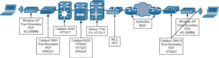
Figure 14-7 shows an example of an abstraction for drivers of cars. The left picture illustrates the steering wheel of a Formula 1 driver. The driver is given a myriad of controls to influence the detailed operation of many elements of the car while driving, such as the braking systems, traction controls, communications with the pits, etc. This is an example of imperative control of a system.

In contrast, the right picture depicts the controls of a regular vehicle. Notice that the driver is presented with the basic controls to operate the vehicle as a whole, not its constituent parts. The steering wheel allows the driver to influence its direction. Pedals are used to determine the speed and displays provide feedback on the car’s current status. This is an example of a declarative control system.
In intent-based networking, the controller’s knowledge of all the devices under its governance is leveraged to help achieve the desired behavior. The goal of providing priority for an application can be reduced to an abstract expression such as “Application X is business critical in my domain.” Such an abstract expression of intent can be interpreted by the controller based on its knowledge of the network. The controller knows all of the network elements under its governance and the network topology. The QoS capabilities of the devices are therefore also known, such as
QoS configuration syntax
Queueing scheduling details (number or priority queues, Weighted Fair Queues (WFQ), Scheduler details)
Possible limitations regarding number of queues, Weighted Random Early Detection (WRED), syntax, etc.
This complete knowledge of the device types, topology, and device capabilities allows the controller to derive the appropriate device configurations automatically. The controller translates the desired behavior into actual device configurations. The derived configurations can then be pushed to the relevant network elements automatically using the southbound APIs described in Chapter 13. Figure 14-8 shows an example of how an abstract expression of intent is expressed to classify an application—a far cry from the current device-centric mode of configuring QoS policies requiring in-depth knowledge of the devices, software, CLI commands, etc.
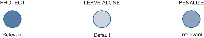
The three application categories are detailed as follows:
Relevant: These applications directly support business objectives. Applications should be classified, marked, and treated marked according to industry best practice recommendations. (RFC 4594)
Default: These applications may/may not support business objectives (e.g., HTTP/HTTPS/SSL). Applications of this type should be treated with a default forwarding service. (RFC 2474)
Irrelevant: These applications do not support business objectives and are typically consumer-oriented. Applications of this type should be treated with a “less-than best effort” service. (RFC 3662)
Note that the application categories have also been standardized by the Internet Engineering Task Force (IETF), as indicated by the RFC references in the list. These standards assist in achieving an industry-wide classification for applications.
The abstractions empowered by the Cisco DNA controller in the architecture allow a much simpler method of operating the network. You as a network operator or network architect can focus on determining the desired behavior of the network (the “what”) rather than worrying about the mechanics of configuring network elements (the “how”).
Other examples of such simplified expressions of intent, as well as the anticipated operational group, are listed in Table 14-2.
Table 14-2 Examples of Expressed Network, Security, or IT Intent
Expressed Intent |
Operational Group |
Execution |
Application X is business critical. |
IT |
Create filters for application X. Configure QoS for application X on all relevant network elements. |
User-group X should receive preferred network access. |
IT |
Configure filters for user-group X. Configure QoS for user-group X on all relevant network elements. |
All IoT devices and applications should be isolated from all enterprise applications, devices, and users. |
Security |
Create a segment for IoT devices. Configure an access control policy for all IoT devices. Associate IoT devices with the IoT segment. |
User X is blocked from network access. |
Security |
Create a filter for user X. Configure an ACL to block user X from network access on all relevant network elements. |
All routers must have a minimum software version X. |
Network |
Create an inventory of running software versions. Initiate an upgrade procedure for all routers to software version X for all noncompliant routers. |
Notice that none of these statements of intent contain network element specifics. They express a desired behavior for the network as a system, for a subset of all network element types, or for the services delivered to users, devices, and applications.
Domain Controllers Versus Control Plane Protocols
The previous discussions introduced the value of network domain controllers to govern the operation of the network as a cohesive system. So what is the relationship between such domain controllers and existing control plane protocols? Do domain controllers replace traditional distributed control plane protocols like Border Gateway Protocol (BGP), Enhanced Interior Gateway Protocol (EIGRP), Open Shortest Path First (OSPF), Protocol-independent Multicast (PIM), Spanning Tree Protocol (STP), and the like?
In Cisco DNA, a distinction is made between the Cisco DNA domain controller functions and network control plane functions. As discussed earlier, the Cisco DNA controller functions govern the operation of a network domain as a whole, instantiating network functions and elements and pushing device configurations using APIs to instantiate expressed intent. The Cisco DNA domain controllers, however, do not replace traditional control plane protocols. Specifically, a domain controller in Cisco DNA does not establish and control real-time forwarding or session state information. This job still remains with network control protocols.
In contrast, the network forwarding control planes focus on the establishment and maintenance of dynamic state—whether this is at Layer 2 for switching, Layer 3 for routing, or even at a higher layer for session-based traffic such as IPsec. These distributed control plane protocols create and maintain state within the network elements for both unicast and multicast traffic. Distributed forwarding or session databases are effectively created and maintained by such control plane protocols. For all routers in a routing domain, a routing protocol creates a distributed Layer 3 forwarding database and ensures that updates are propagated as the state of the network changes. For all switches in the network, a similar forwarding database is created based on Media Access Control (MAC) addresses. For example, STP ensures that such Layer 2 topologies do not create any forwarding loops. Again, the protocol offers an update mechanism to maintain a correct forwarding state as the topology changes (for example, when switches are added or fail).
Note that the network control plane functions no longer need to run based on protocols between a set of network elements. Figure 14-9 illustrates some recent examples in the networking industry of control plane architecture evolutions. The traditional architecture based on protocol exchanges between network elements is shown as model 1. Models 2 and 3 illustrates the concept of off-box network control planes. In model 2, the individual network elements no longer run the protocols required to determine forwarding or session states. These computations are completely centralized in an off-box function that may also have visibility of multiple network elements. Algorithms based on graph theory determine an optimal forwarding state and push this state via APIs into the network elements. Model 3 is a variant of such a centralized forwarding control plane, where only a subset of the computation is centralized off-box, supported by some on-box computations. The third model pertains to overlay networks, where both the virtual data plane and control plane are created on demand, decoupled from the hardware-specific capabilities of the individual network elements. Multiple overlay networks with their respective forwarding and control planes are established in parallel. The fourth model illustrates the approach taken in an IBN architecture. The distributed or centralized forwarding control planes are complemented by policy agents that may aid in the translation and instantiation of policy.
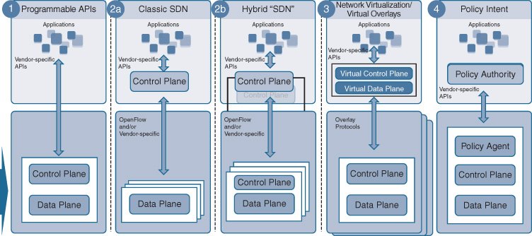
The approach taken in Cisco DNA is model 4. Forwarding and session control plane protocols are not replaced by the Cisco DNA domain controllers. Instead, they are leveraged to continue with the determination of the computation of the dynamic forwarding state. The Cisco DNA controller focuses on the instantiation and configuration of the network elements, as well as governing the behavior of the network elements as constituent components in the overall architecture. Note that as part of this determination, the Cisco DNA domain controllers may govern the control plane functions. For example, upon instantiation of a network element, a configuration with the initial routing protocol configuration may be pushed. But the Cisco DNA controllers do not participate in or execute the dynamic computations of forwarding or session states.
Automating Your Network with Cisco DNA Center
So far this chapter introduced the topic of network automation to augment the capabilities offered by device programmability. It highlighted the need for network-wide automation capabilities in a network supporting digitalized business processes, and some of the challenges that operators face to increase their level of automation.
Network domain controllers provide the capabilities to operate on the network as a system, rather than as a loose collection of individual physical or virtual network elements of different types. The abstractions offered by a network controller function enables expressions of intent, where you can describe at a network level what the network’s behavior should be, rather than worrying about the technicalities of programming individual devices and functions.
This section delves into the details that the Cisco DNA Center platform offers in the overall architecture, in particular from an automation perspective. This section explores base controller capabilities, such as keeping an inventory of all devices with all relevant metadata, or maintaining a topology model. It also demonstrates how Cisco DNA Center simplifies your network operations by offering software image management functions and assisting in license management. Finally, it explores in detail functions automating the deployment of network elements, as well as ongoing lifecycle management.
Cisco DNA Center Basics
The Cisco DNA Center platform allows you to manage all aspects of operating your enterprise network domain, including routers, switches, wireless access points, and their supporting network functions (WLAN controllers, DNS, DHCP, etc.). The platform is designed around workflows and Automation and Assurance tools.
Cisco DNA Center workflows allow you to automate the full lifecycle of your enterprise network, including the following phases:
Design
Provision
Assurance
Policy (Intent)
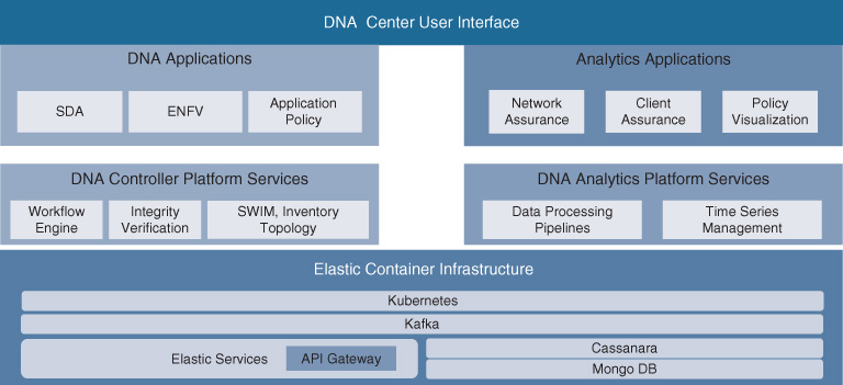
Automation and Assurance tools offer the capability to execute standard automation functions, such as discovering devices in the network, maintaining an inventory of all network elements and functions, viewing the network topology, and managing licenses. Figure 14-10 illustrates the overall software architecture of Cisco DNA Center. The platform is built on a state-of-the-art software architecture. Its capabilities and applications are implemented as microservices running on top of a container scale-out architecture. The Cisco DNA Center platform infrastructure offers common capabilities such as support for role-based access control (RBAC), Datagram Transport Layer Security (DTLS) secure channel communication, common database repositories for state data, and resource management. The Cisco DNA controller and analytics/assurance functions are the main components sitting above the Cisco DNA Center platform infrastructure.
On the automation side, a common service automation framework offers the capability to create network services orchestration applications. The intent expressed via the GUI is internally mapped to a customer-facing service (CFS) model. Such models representing the intent are abstracted for the end-to-end network. The workflow engine has the capabilities to break this internal end-to-end CFS model into individual abstracted device models, referred to as resource-facing service (RFS) models. These RFS models are still abstracted. They do not reflect specific capabilities of a particular device, but rather express the service in a device-type agnostic model. Finally, the automation infrastructure provides the capabilities to convert the device-type agnostic RFS models into actual device-specific models and commands that can be programmed into each participating device using the device programmability APIs.
An example of such a Cisco DNA Center internal model transformation is as follows:
User intent: Application X is business critical throughout my network.
CFS: Application X gets higher priority than best-effort applications.
RFS:
Routers: Place traffic from Application X into a Low-latency Queue (LLQ).
Switches: Place traffic from Application X into a WFQ and implement WRED.
Device models: Provide device-specific commands/APIs based on the platform type and software version to instantiate the RFS in the particular device.
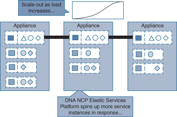
Figure 14-11 illustrates the advantages of the underlying scale-out architecture that Cisco DNA Center is based on. Application microservices for automation and analytics run on a Cisco DNA Center appliance. In case the demand for a particular micro-service increases, the platform has the capability to instantiate additional containers.
The user interface is the component in the Cisco DNA Center architecture that exposes these capabilities to the operator. Figure 14-12 shows the initial Cisco DNA Center landing screen from which you can control your enterprise network domain.
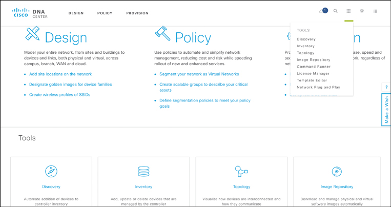
The remainder of this section focuses on the automation-related capabilities: standard applications such as Discovery, Inventory, and Topology (shown in the Tools menu in Figure 14-12), as well as the Design and Provision workflows. The Assurance workflow (not shown in Figure 14-12) and Policy workflow are discussed in detail in Chapter 19, “Cisco DNA Software Defined Access,” Chapter 20, “Cisco DNA Application Policy,” and Chapter 21, “Cisco DNA Assurance.”
Note that Cisco DNA Center supports both physical and virtual network elements.
Device Discovery, Inventory, and Topology
At the heart of the Cisco DNA Center platform are the device Discovery, Inventory, and Topology applications. Recall that the goal of automation is to perform standard and nonstandard operations consistently on a set of network elements simultaneously. The controller function of Cisco DNA Center needs to become aware of all the devices that exist in the network under its governance. The first task in the operation is to establish an inventory of all network elements and functions by executing the device Discovery application.
Figure 14-13 shows the Discovery user interface to discover the devices in your network and add them to the Cisco DNA Center inventory.
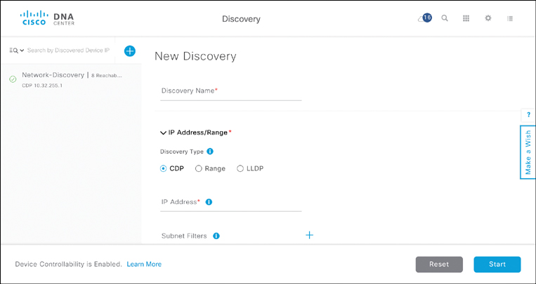
Device discovery operates based on either
Cisco Discovery Protocol (CDP)
IP address range
Link Layer Discovery Protocol (LLDP)
Both LLDP and CDP are protocols to share information about directly connected devices. Both protocols offer the capability to advertise a device’s identity, its capabilities (e.g., operating system or IP address), and neighbors. Using the IP Address/Range option allows you to perform a similar discovery based on a range of IP addresses that you enter in the GUI. Cisco DNA Discovery then sweeps across the entered range, querying each device in the range for its details.
Devices that are discovered using the Discovery application or those that were provisioned by Cisco DNA Center as part of the Provision workflow are then tracked in the Inventory application. The Inventory application gives you insights into all of the devices known to Cisco DNA Center, forming the basis for many of the subsequent operations. The Inventory application summarizes the pertinent information of all known devices in its initial screen, illustrated in Figure 14-14.
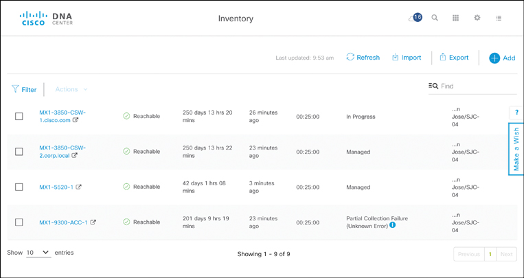
Details such as device name, management IP address, reachability status, operational uptime, and location are tracked for each device. You can also select one or more elements in the inventory list and perform basic operations such as
Update the device credentials
Update the resync interval
Resynchronize the device with the inventory
Delete the device from the inventory
Launch the Command Runner application to execute CLI commands
A filter function allows you to view a subset of all devices in the inventory based on any of the metadata fields. For example, you can filter out a subset of elements based on the device name, MAC address, IP address, reachability status (reachable, unreachable), IOS/firmware version, platform, serial number, uptime, last update time, resync interval, last inventory collection status, device role, location, device family, or device series. Wildcards can be used in the filter specifications. The filter function is particularly useful to automate a large network with possibly thousands of devices, allowing you to select the appropriate subset of devices for the desired operation.
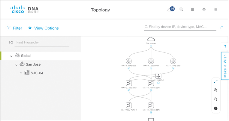
The Topology application in Cisco DNA Center then allows you to view the network topology of your enterprise routers, switches, access points, and supporting devices. This is particularly helpful to understand the structure of your Cisco DNA architecture. It also helps you to verify that the actual state of the architecture matches your intent. The topology is thus an integral part of the Assurance functionality of Cisco DNA Center discussed in Chapter 21. Having a solid understanding of the topology also helps in troubleshooting issues.
Figure 14-15 illustrates an example of the network Topology application of Cisco DNA Center. The different device types—routers, switches, access points, and hosts—are represented by respective icons. A set of multiple elements is represented in collapsed mode, with the caption indicating the number of network devices that are actually in the topology (16 in this example). Alternatively, an expanded view allows you to see all the devices and their links to adjacent devices individually. Again, a filter option is available to zoom in on a particular subset of devices based on VRF, VLAN, or routing protocol. Selecting a device in the Topology application reveals its metadata details, such as the management IP address, software version, device family, MAC address, or platform.
Day 0 Operations—Standardizing on Network Designs
Recall from the previous discussion that the fundamental prerequisite to automation is standardization. Cisco DNA Center provides support to drive standardization into your architecture starting with the Design workflow.
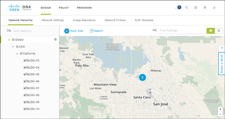
The Design workflow allows you to express your intended enterprise network architecture, starting with the geographical characterization of the topology. The Network Hierarchy screen allows you to specify the structure of your architecture in terms of sites, buildings, and floors. A site or area is associated with a geographic location, allowing for a map-based view in addition to a list view. Sites may have one or more buildings. A building can consist of one or more floors, a property that is particularly relevant for the wireless automation and assurance functions.
The concepts of sites, buildings, and floors are fundamental to the Cisco DNA Center design phase. The purpose of the Design workflow is to allow a network architect to specify a network architecture template. For example, a small site may be defined in your enterprise to contain a single WAN router to which two access switches connect. Wired hosts or wireless access points in turn connect to the access switches. Such a simple design with associated parameters (device types, initial device configurations, IP addresses, etc.) can be stored in an architecture design template, and subsequently associated with a site or a building. Furthermore, standard settings can be applied at any level of the hierarchy and inherited down to lower levels. For example, settings applied to a site are by default inherited into buildings.
Representing your network in such a hierarchy also allows for the flexibility to accommodate site- or location-specific differences. For example, you may want to operate a separate DNS or DHCP server in different regions of your network. A hierarchical representation of your architecture also allows for the default inheritance to be overridden. A different set of standards can be applied to different parts of the network hierarchy if desired. Figure 14-16 shows the Network Hierarchy screen with a geographical map of the network sites and a list of the site hierarchy on the left.
Standardizing Settings for Supporting Network Functions
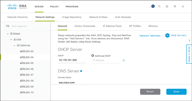
An example of such standard network settings are the details to reach auxiliary network functions such as Network Time Protocol (NTP), DHCP, DNS, Syslog, or other servers. Reachability to these network functions is critical for the operation of the network, and hence even the slightest misconfiguration can have disastrous effects on the network. Often, these functions are operated on a regional basis, administered by different teams.
The Network Settings screen in the Cisco DNA Center Design workflow allows you to standardize and automate reachability to such auxiliary network functions. Figure 14-17 shows the details of the parameters to standardize on such network settings. The IP addresses of primary or secondary servers are entered, as well as the time zone and message-of-the-day banners. Note that the network hierarchy concept outlined here provides the flexibility to apply settings on a network-wide basis, or to override them if regional or even site-specific parameters apply. The green bar on the network hierarchy navigation pane on the right indicates the current scope of the parameters. By default, settings entered in the global scope are inherited down to sites and buildings. Selecting a particular lower-level hierarchy allows you to overwrite the global settings, breaking the inheritance if desired.
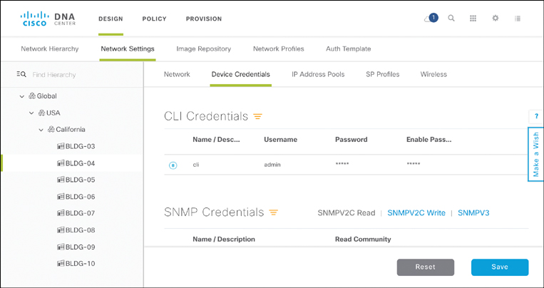
Automating Device Credentials
Another example of seemingly mundane settings that may have disastrous effects if misconfigured are device credentials. These are critical for the Cisco DNA controller to continuously monitor the devices’ state and configurations. After all, for the Cisco DNA controller to function it requires a full view of all the network elements and functions under its governance. The Cisco DNA controller periodically verifies that the state and configuration it has in its device and topology model database still reflects the current state in the devices themselves. Being able to log in and monitor the device states is thus critical.
Figure 14-18 illustrates the parameters to control the device credentials. CLI, HTTP(S), and SNMP credentials are currently supported.
Reserving and Managing IP Address Pools
Another example of a standard that can be enforced in the Cisco DNA Center controller is the use of IP addresses. Again, misconfigurations of IP addresses in devices or overlapping use of IP addresses can be major causes for disruptions in the IP communication patterns, especially if these addresses pertain to network elements as opposed to end hosts.
Cisco DNA Center allows you to reserve IP address pools and associate them with particular deployments, such as sites or in network design templates, in the corresponding design workflows.
Figure 14-19 shows the Cisco DNA Center user interface to reserve IP address pools for specific uses. Each reserved pool is associated with a label, a subnet mask to characterize its size, the gateway IP address for the pool, and optional DNS/DHCP server addresses. The user interface also reflects the current usage of the pool, indicating how many of the IP addresses were already allocated during provisioning activities.
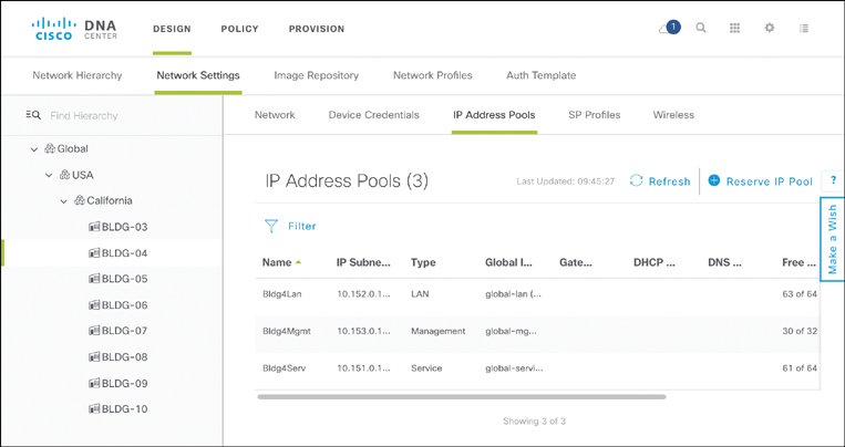
Note that Cisco DNA Center also allows integration with an external IP address management (IPAM) system such as Infoblox or BlueCat. The Cisco Digital Network Architecture Center User Guide3 provides additional details on how to import an address pool from an external IPAM system.
3 https://www.cisco.com/c/en/us/td/docs/cloud-systems-management/network-automation-and-management/dna-center/1-1/user_guide/b_dnac_ug_1_1.html
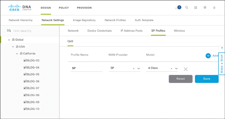
Standardizing Service Provider QoS Profiles
Yet another example of settings that Cisco DNA Center helps to standardize across your infrastructure are the quality of service (QoS) settings used for site connectivity provided by service providers. Navigating within the Design workflow Network Settings screen to the SP Profiles QoS tab allows you to template different QoS models that you contracted from one or more service providers in your network. The SP Profiles tab allows you to store different templates, identified by a name and a tag representing the SP, and characterizing the number of queues that the QoS profile implements.
These templates are subsequently referred to when you design your site profiles. For example, creating a virtualized system architecture for a branch requires you to characterize the SP that provides the WAN connectivity. The SP Profile entered in this step of the Design workflow is referenced in subsequent Cisco DNA Center configuration workflows (e.g. the Routing and NFV network profile workflow). This allows you to ensure greater consistency across all sites being served by the same SP in your network from a QoS perspective. Figure 14-20 shows how SP QoS settings can be added as templates into Cisco DNA Center.
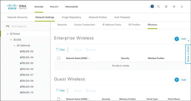
Characterizing Wireless LAN Profiles
Finally, the Network Settings tab allows you to template the WLAN settings that are applied in the wireless deployments in your network. Settings such as the SSID or RF profiles can again be stored in a template repository, to be referenced against in the later deployment workflow when a wireless AP is provisioned.
Figure 14-21 illustrates some of the options to standardize wireless settings.
Standardizing on Network Designs
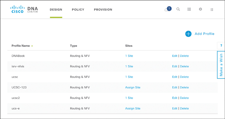
The beginning of this chapter outlined the complications that can arise in operating a network from nonstandard site architectures and device configurations. The Cisco DNA Center Design workflow Network Profiles screen allows you as an architect to create standardized templates for your network elements and site topologies. As in the case with standard network settings, these can be applied during the Provision workflow to devices in your various sites as they are deployed.
The Network Profiles screen starts with the inventory of all template designs. This allows you to see all the templates that are stored in the Cisco DNA Center library, identified by template name. The inventory also lists the type of profile. Currently, network profiles can be of type routing and virtualization, switching, and wireless. The inventory also provides an indication of the deployment of a particular profile. The association of the intended design to an actual deployment is done via a site. Once you have added an architecture template to the inventory, you can associate it with one or more sites. During the Provision workflow, devices are also associated with a site. Sites are thus common anchors to which both design templates and actual devices are associated, allowing for the templates to be applied in all the devices of a site. An example of a network profile library in Cisco DNA Center is illustrated in Figure 14-22.
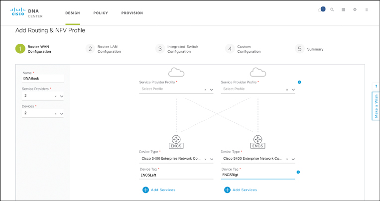
Additional site architecture profiles are added by clicking the Add Profile option. This initiates the Cisco DNA Center Profile Design workflow for routing and NFV, switching, or wireless. In the example of a virtualized branch, the initial workflow screen shown in Figure 14-23 is displayed. The generic branch architecture is specified, with options for a single or dual WAN router deployment, as well as a selection of the WAN router type. Notice that you can apply the SP Profile specified in an earlier step of the network design workflow, characterizing the QoS profile that is to be applied toward the WAN.
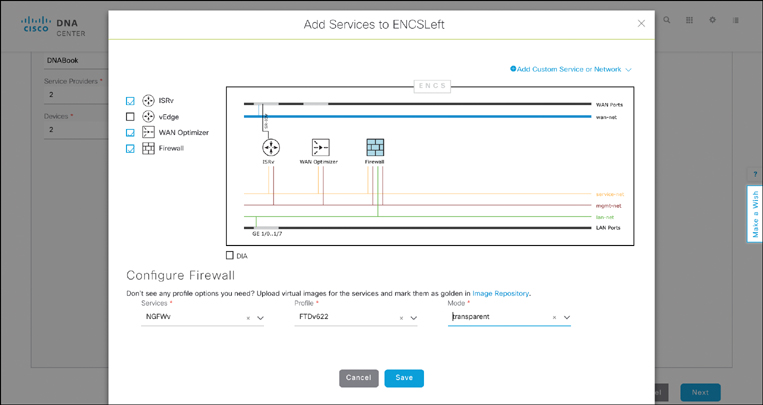
In the case of a virtualized branch, additional virtual network functions (VNF) are added to the template. This is achieved by clicking the Add Services option in the workflow. A canvas appears, allowing you to select among the known VNF types. In the case of a virtualized branch, the internal VLAN connectivity between the VNFs is built in based on validated designs. The canvas represents a segment connecting the LAN ports to the LAN network, the WAN ports to the WAN network, and any inter-VNF segments to the service network. The DIA option allows for a VNF of type Firewall to front-end the WAN connection, instead of a virtual WAN router.
For each type of VNF added to the design, you can select an actual product. For example, if you select a virtual router in your design, you can subsequently specify for a Cisco Integrated Services Virtual Router (ISRv) to be instantiated. An additional parameter allows you to determine some of the profile characteristics for the VNF. The VNF profiles define how many resources are associated with the virtual machine in terms of vCPUs, virtual memory, or virtual storage. These are important parameters to validate the total resource demand against the x86-based host capacities when the device is brought to life. Figure 14-24 shows a sample canvas for specifying a virtual branch template with different VNFs in Cisco DNA Center.
At this stage in the design process, not all parameters can be completely determined. Any site-specific variables, such as IP addresses, cannot be built into the template by definition. Such parameters are completed during the Provision workflow, where the template is applied to a particular site deployment.
The Network profile workflow allows for additional parameters to be associated with the template. For example, whether the LAN ports are to be configured as access or trunk ports, VLAN settings on the physical interfaces, parameters for the internal virtual switch in Cisco Enterprise NFV Infrastructure Software (NFVIS), or even if a particular configuration snippet should be applied upon device instantiation. Details of these steps are found in Chapter 18, “Cisco DNA Virtualization Solutions: Enterprise Network Function Virtualization and Secure Agile Exchange.”
At the end of the Network profile workflow, Cisco DNA Center validates the template to ensure that all parameters are correctly specified. In the case of Enterprise Network Function Virtualization (ENFV), a guidance is offered to ensure that the resource requirements of all the VNFs in terms of virtual CPUs (vCPU), memory, and storage, do not exceed the capacity of the specified x86-based host type.
Automating the Deployment of Network Elements and Functions
The Design workflow described in the previous section is a fundamental prerequisite to enable network automation in a digitalized network architecture. The next step in the automation journey is to leverage Cisco DNA Center workflows to automatically deploy new network elements. This step is covered by the Provision workflow.
As briefly introduced, the concept of sites is critical to associate an actual deployment with a site architecture profile to increase the level of standardization in your network. A particular network design profile is associated with one or more sites. Similarly, as you provision a device, you also select the site in which the device is located. The association of both the device to be provisioned and the design template to a site allows Cisco DNA Center to correlate the two. At a high level, the workflow follows this sequence of events:
One or more devices are shipped to a site for deployment.
A local operator (not necessarily CCIE qualified!) performs the physical deployment of the device(s)—cabling of power and physical connections.
The devices are powered on.
The Network Plug and Play Client function is automatically activated upon power-up. This process sends a message to Cisco DNA Center with the device’s details, such as its serial number and type.
Cisco DNA Center adds the device to its unclaimed inventory.
The Cisco DNA Center Provision workflow is performed by a network operator.
The unclaimed device is selected for provisioning.
The unclaimed device is associated with a site in Cisco DNA Center.
Cisco DNA Center finds the corresponding site template, checks that the device types match, and if successful pushes the device configuration using Representational State Transfer (REST) API calls to the device.
The device on site then executes the configurations pushed by Cisco DNA Center.
In the example of an x86-based host configured for ENFV, the VNFs specified in the ENFV template are instantiated and networked as per the design template.
Various options are supported to perform the plug-and-play capability of a device. First, the device leverages DHCP with Option 43. In this case, the DHCP server returns the details of the Cisco DNA Center controller acting as the Plug and Play (PnP) server in the DHCP response. The device thus learns from DHCP which Cisco DNA Center instance to contact to complete its provisioning process. Second, DNS may be leveraged to obtain the required information. In this case, the DNS server maps the URL pnpserver.localdomain to the IP address of the PnP Server running in Cisco DNA Center. The third option to perform zero-touch provisioning of a device involves contacting a Cisco cloud service. In this option, the URL https://devicehelper.cisco.com/device-helper again is redirected to the IP address of the Cisco DNA Center instance. Notice that the URL is in the domain cisco.com. Fourth, a local operator leverages the USB port on a physical device to be provisioned to provide a bootstrap file, again providing the required details to contact the PnP server. And last, Cisco also offers an installer app for onsite operators. This application runs on a hand-held device, and again provides the details of the PnP server running in Cisco DNA Center.
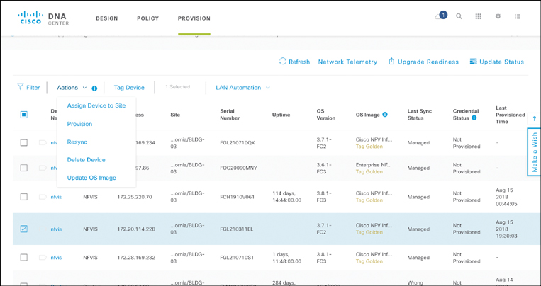
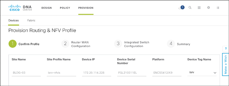
After the device registers itself with the PnP server running in Cisco DNA Center, it is placed in an unclaimed device inventory list. This is the basis for the subsequent provisioning step: providing the required variables and site-specific details for the final deployment. Figure 14-25 illustrates the initial provisioning screen for unclaimed devices. Select one or more devices in the workflow. The option Assign Device to Site creates the association of that device with a particular site in your network hierarchy. This allows Cisco DNA Center to also create the correlation to the design template for the specified site. The option Provision then kicks off the provisioning step, where the design profile is applied and the device is provisioned using the REST API calls from Cisco DNA Center to the device to be provisioned.
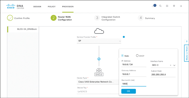
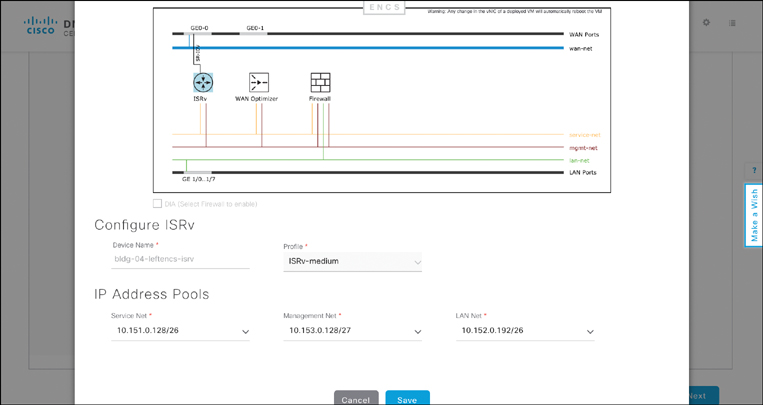
Recall that not all parameters can be determined at the design stage. Some variables in a design are site-specific. Part of the Provision workflow is thus to allow you to enter those site-specific parameters. Figures 14-26, 14-27, and 14-28 illustrate some examples of such parameters in the case of a virtual branch deployment, allowing you to verify the profile to be applied to the device in question, to provide the details for the WAN interface to the service provider at the site, and to specify IP addressing details of a virtual router (as an example). Other site-specific variables follow similar templates to allow the site or device provisioning to complete.
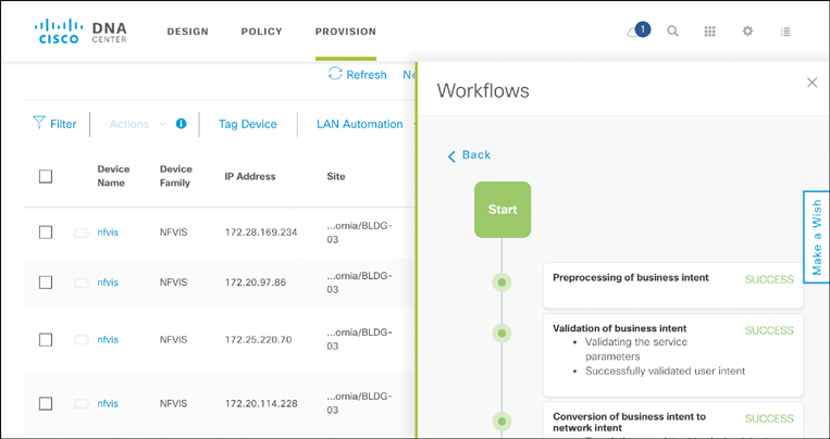
At the end of the Provision workflow, the operator initiates the actual provisioning process. This triggers a set of API calls from Cisco DNA Center to the device to be provisioned. The sequence of events is monitored from within Cisco DNA Center to ensure that the automated process proceeds as intended. Figure 14-29 shows an example of the deployment steps, with details of each activity and the associated timestamps. The actual payload of the API call from Cisco DNA Center to the device is also displayed for verification purposes.
Day N Operations—Automating Lifecycle Operations
The last leg in the Cisco DNA automation journey is the ongoing maintenance and update of the deployed devices. The tools and functions previously described—Inventory, Topology, Design templates—also play a role in this phase. They allow you to push updates to your configurations or template architectures to one or more devices in your network hierarchy.
Two applications are worth mentioning for day N operations: software image management and license management. As previously indicated, these are applications that run as part of Cisco DNA Center to allow you to perform ongoing management of your software images and licenses, respectively.
Figure 14-30 shows the capabilities of the Software Image Management (SWIM) application. Software images for the various devices in your network are added to Cisco DNA Center’s Image Repository. This is done from a local machine with which the operator connects to Cisco DNA Center. Alternatively, software images are uploaded from a specified URL. Once uploaded, the software image is associated with a device family (routers, switches, access points, for example) and also marked as “golden.” Golden images are those images that you have certified for deployment in your network, or that you wish to standardize on throughout your infrastructure.
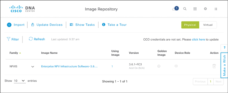
A day N software image upgrade process is then initiated from the Image Repository application by selecting the option Update Devices. You as an operator can select one or more devices as a target for the software upgrades. The Cisco DNA Center SWIM application then performs a number of checks to validate the upgrade. For example, memory and hard disks are verified for sufficient space to perform the software upgrade. If the pre-checks are successful, the new software images are pushed to the selected devices and activated. Finally, a set of post-checks are executed to ensure that the software upgrade was successful. At any stage in this process, a rollback procedure is activated in case a particular step in the upgrade fails.
The License Manager application running on top of Cisco DNA Center allows you to perform similar day N operations for licenses. The application is linked to the Cisco Smart Licensing capability. View the purchased licenses by device type, how many devices are in your network of a particular type that require a license, as well as how many licenses out of the purchased pool are currently in use. The License Manager application also provides you compliance details, such as the expiration dates for time-based licenses in your pool.
Summary
This chapter explored the topic of network automation as a main capability of the Cisco Digital Network Architecture. While many enterprises realize the potential and necessity to automate their network operations, multiple challenges still create roadblocks for an increased level of automated operations. Examples of such roadblocks include nonstandard “snowflake” deployments from the historical evolution of many networks, and reservations of IT and network operations staff that they may become obsolete.
The topic of network automation extends the capabilities offered by device programmability to the network level. Rather than operating on a device-by-device basis, network automation aims to treat the network as a coherent system in itself. Operations are applied to the network to achieve a desired behavior, rather than pushing configurations to individual devices. This subtle but important distinction forms the basis for intent-based networking, where network operators are encouraged to describe the intended behavior of the network, rather than configuring devices one by one. Intent-based networking focuses on what the network should do for users, devices, and applications, rather than how the individual elements are configured. The chapter introduced the Cisco DNA controller as a fundamental element in the overall Cisco Digital Network Architecture to enable intent-based networking and the supporting abstraction levels. The key takeaways of this chapter are as follows:
Standardization is a prerequisite to any automation paradigm. Both standard and nonstandard operations are addressed in Cisco DNA Center, the platform in Cisco DNA to enable network-wide automation.
Cisco DNA Center supports automation tools for standard processes (Inventory, Discovery, Topology, Network Plug and Play). In addition, Cisco DNA Center supports sophisticated workflows to operate all stages of your Cisco DNA network: Design, Policy, Provision, and Assurance.
The Cisco DNA Center Design workflow is particularly important to drive standards into your Cisco DNA network. Settings such as IP addresses of common network functions (DNS, DHCP, Syslog, and NTP servers, for example) can be standardized and automated. The Design workflow also accommodates the creation of standard site and device templates that are stored in a library to be applied in the provisioning phase of the network.
The Cisco DNA Center Provision workflow supports Network Plug-and-Play, allowing you to ship network elements to your sites and automatically provision them. Once a device calls home to the Cisco DNA Center plug-and-play server using one of multiple mechanisms, the appropriate design template can be applied.
While automation is an important and even essential capability of an intent-based network architecture, it must be complemented by the corresponding analytics and assurance functions. These allow you to verify that the intended and automated capabilities are indeed deployed and operational in your network at any point in time. The topic of network analytics and assurance is thus the next milestone in the journey to enable the Cisco Digital Network Architecture. You may not be surprised that Cisco DNA Center again plays a major role!
Further Reading
Cisco Systems. Cisco Digital Network Architecture Center User Guide, Release 1.2.1. Updated August 13, 2018. https://www.cisco.com/c/en/us/td/docs/cloud-systems-management/network-automation-and-management/dna-center/1-2-1/user_guide/b_dnac_ug_1_2_1.html.
Staffing Industry Analysts (SIA). “IT Employers to Add Staff but Facing Tech Skills Shortage, Hays Reports.” Feb. 1, 2018. https://www2.staffingindustry.com/row/Editorial/IT-Staffing-Report/Feb.-1-2018/IT-employers-to-add-staff-but-facing-tech-skills-shortage-Hays-reports?.
Gartner, “IT Budget: Enterprise Comparison Tool”, http://www.gartner.com/downloads/public/explore/metricsAndTools/ITBudget_Sample_2012.pdf