Extensions are simple external programs that perform some actions on the selected objects in the document. They are represented by the commands in the submenus of the Extensions menu. However, they should not be confused with path effects; they are one-off, destructive operations that change objects without preserving the originals. The only way to reverse the effect of an extension command is by using Edit ▸ Undo.
A typical extension has a number of parameters you can set in a dialog before running the extension. Most extension dialogs have the Live preview checkbox which, when checked, lets you preview the effect of various parameters in the document without having to undo and call the extension again. Note that while the Live preview is off, the extension dialog is not modal, which means you can pan the canvas and select different objects; as soon as you turn Live preview on, the dialog locks the rest of Inkscape so you can only change the parameters in the dialog and see their effect on the current selection. (There’s usually a pause between changing the parameters and updating the canvas with Live preview.) To apply the changes as final, click the Apply button; to cancel without applying, click Close.
Not all extensions deal with paths; some extensions were already mentioned where it was relevant, and others will be covered throughout the book. In this chapter, we will look only at the extensions that modify or create path objects.
In the Generate from Path submenu, there are several extensions that take the selected path and generate some new path or paths from it:
Inset/Outset Halo
Adds to the selected path a specified number of inset or outset paths, spaced by a given distance, each further offset having lower and lower opacity. This may be an acceptable choice if you want to blur the edge of your object but don’t want to use the Gaussian Blur filter (17.1 Blur):
Extrude
Creates a primitive 3D effect by extruding the selected path at a given angle to a given distance. The result of the effect is a group of two objects, one being the original path and the other its extrusion skirt, which you can style differently, as shown in Figure 13-30.
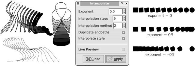
Creates an interpolation, or blend, between two paths—a sequence of intermediate paths that smoothly transition between the two paths. You can specify the number of the Interpolation steps and the Exponent, which, if different from the default 0, shifts the blend toward one of the ends:
The Interpolate style option, although marked “experimental,” worked well enough in my tests. The two interpolation methods differ slightly in the way they generate intermediate steps. The extension generates all the intermediate steps as a group of paths; the Duplicate endpaths option adds copies of the original paths to this group as well. Since interpolation always connects beginnings and ends of the two paths, you may need to reverse one of the paths (Path ▸ Reverse) in order to get the result you want.
Pattern Along Path
This is similar to the path effect of the same name (13.1.3 Pattern Along Path and Bend) and, in fact, is the first version of this functionality, introduced before path effects became possible. Currently, the extension has one advantage compared to the path effect: It can use a group of objects (each with its own style) as the pattern, whereas in the path effect you are limited to a single-pattern path. To use the extension, select the pattern path or group and the skeleton path (the pattern must be on top of the skeleton in z-order) and choose the extension from the menu. Its options are similar to those for the corresponding path effect.
The Modify Path submenu contains extensions that change the selected path directly:
This useful extension creates more nodes in the path without changing its shape. You can specify either the maximum allowed distance between adjacent nodes or the number of segments into which each segment will be divided. We’ve seen this extension in action in Figure 9-11.
Envelope and Perspective
Both of these extensions require that you select two paths, the second being exactly four nodes long. This second path is treated as a deformation envelope into which the first path is inscribed (only the coordinates of the corners matter; curvature of the sides, if any, is ignored). These extensions have no parameters. The only difference between the two extensions is that Perspective, unlike Envelope, interprets the four-node envelope as a perspective plane, performing foreshortening so that parts “farther away” are made smaller:
Flatten Béziers and Straighten Segments
The Flatten Béziers extension approximates each Bézier curve in the selected path with a sequence of straight line segments (the higher Flatness is, the rougher the approximation), whereas Straighten Segments simply shortens all Bézier handles by the given percent, so that setting this to 100 percent turns each Bézier curve into a straight line segment:
Jitter Nodes
This extension randomizes the selected path by displacing all nodes in random directions and at random distances, limited by the Maximum displacement parameters, which can be set separately for X and Y (for example, set maximum displacement for X to 0 if you want the nodes to be jittered only vertically). Also, you can separately enable jittering for nodes themselves and for their Bézier handles. Turn Use normal distribution on to make smaller displacements more probable than large ones; without it, any displacement within the Maximum displacement limits is equally probable.
Fractalize
This is another way to randomize a path. Unlike Jitter Nodes, it creates new nodes between existing nodes itself, and then moves these new nodes (any Bézier handles in the original path are discarded) leaving all the original nodes in place. The Subdivisions parameter determines how many times each segment will be subdivided in two (caution: Increasing this value makes the node count grow exponentially—for example, 10 subdivisions turn a two-node path into one with 1,025 nodes), whereas Smoothness changes how far the new nodes can move (lower Smoothness produces a rougher path). This effect is perfect for creating coastal lines in fantasy maps:
Rubber Stretch
This extension stretches the object vertically (rotate it before and after applying the extension if you want a different stretch direction) while blowing it horizontally on the sides, making it behave in a nonlinear way as if made of rubber:
This distorts the selected path into a whirl, its center being in the center of view in Inkscape when you start the extension. You can always place the center of view at the geometric center of selection by pressing
 or choosing View ▸ Zoom ▸ Selection (3.9 The Zoom Tool). This extension gives better results if you add more nodes to the source path, either by
  in the Node tool (12.5.3 Deleting and Creating Nodes) or via the Add Nodes extension:
The Render submenu contains extensions that generate entirely new objects not based on anything in your document:
Grid
This extension generates a rectangular grid as a single path, each line being a subpath (such as the grid in Figure 13-36). You can set the number of horizontal and vertical lines and the spacing.
Barcode
This is a universal barcode generator supporting a number of common barcode standards (EAN8, EAN13, Code39, and others).
Function Plotter
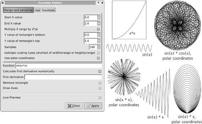
This is a complex extension that draws a graph of an arbitrary function in Cartesian (rectangular) or polar coordinates. Before calling this extension, draw or select a rectangle that will define the scale of the graph; the first four numeric parameters define the ranges of the X and Y coordinates. The Multiply X range by 2*pi checkbox is convenient for trigonometric functions; when it’s checked, the X range of, for example, 0 to 2 is treated as 0 to 2 × π. The Use polar coordinates checkbox transforms the graph into a circle, centered at the center of the original rectangle, with the X range mapped to the angle and Y to the radius.
The Samples parameter sets the total number of times the function will be sampled, at points equidistant on the X axis; since each sampling produces a node, this is also the total number of nodes in the generated path. The higher this number, the more precise the graph. The optimum number of samples, however, depends on the nature of your function; for example, if you’re using a periodic function with n periods in the X range, you will need at least several samples per period to reproduce it with any fidelity.
The function itself must be written using the syntax of the Python programming language. It can use a number of built-in mathematical functions such as
sin(x),log(x), orsqrt(x); refer to the Functions tab for a full list.Each sampling of the function creates a smooth Bézier node; the first derivative of the function at that point is what determines the angle of the handles of that node. You can ask the extension to Calculate first derivative numerically, or you can uncheck that checkbox and provide the derivative function analytically, using the same Python syntax and built-in functions as for the function itself (for example, the first derivative of
sin(x)iscos(x)).
L-system
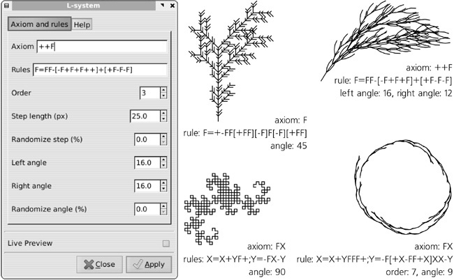
This extension implements Lindenmeyer systems—a simple graphic language with recursion that can produce complex sequential or tree-like structures:
The “program” in this language, built of simple commands like “draw one step forward” or “turn left,” contains two parts: the Axiom and the Rules for substitution. The rules are applied to the axiom as many times as specified by the Order. The rest of the parameters determine the length and angles produced by the primitive commands in the axiom and rules and allow you to randomize these values to render the result more natural. For a complete list of the commands recognized in the axiom and rules, refer to the Help tab.
Random Tree
This is similar to the L-system extension but is much more primitive; all it does is draw a randomly branching tree, where the first segment of the trunk is Initial size long, and each subsequent branch is progressively shorter, until the Minimum size is reached and the drawing terminates. Thus, the bigger the difference between the initial and minimum sizes, the more complex the tree.
Spirograph
This is an implementation of the popular toy of the same name, in which a small circle rolls along the edge of a larger circular hole. In the extension, you can vary the diameters of these two circles and some other parameters.
Finally, the Visualize Path submenu collects extensions that, in one way or another, visualize the selected path:
Number Nodes
This replaces a path with a group of dots, each dot corresponding to the node of the original path, numbered sequentially. You can change the size of the dots and the font size of the text objects that represent the numbers.
Draw Handles
This extension adds lines that correspond to the Bézier handles of the selected path, as a new path with separate subpaths.
Dimensions
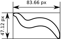
This creates a frame and dimension lines around the selected object (not necessarily a path), such as those used on plans or technical drafts. After creating dimension lines, you can use the Measure Path extension to add the actual length measurements.
Measure Path
This extension calculates the length of the path, from start to finish, and adds this value as a text-on-path object put on the source path (15.7 Converting Text to Path). You can specify the Precision and the Length Unit of the value and adjust the Font size and the distance from the path (Offset).


