2
Structural Patterns
STRUCTURAL PATTERNS
Critical to thinking about an architectural idea and developing its potential is understanding how it might be structured. The spatial and formal essence of an architectural scheme and the structuring of the idea go hand in hand; each informs the other. To illustrate this symbiotic relationship, this chapter describes the development of structural patterns and how they influence the formal composition and spatial layout embedded in an architectural idea.
This chapter begins with both regular and irregular grid patterns, and then discusses transitional and contextual patterns.
- Structural patterns: patterns of supports, spanning systems, and lateral-force-resisting elements
- Spatial patterns: spatial compositions inferred by the choice of a structural system
- Contextual patterns: arrangements or conditions dictated by the nature and context of a site
Analysis based on the Museum of Modern Art, Gunma Prefecture, Japan, 1971–1974, Arata Isozaki
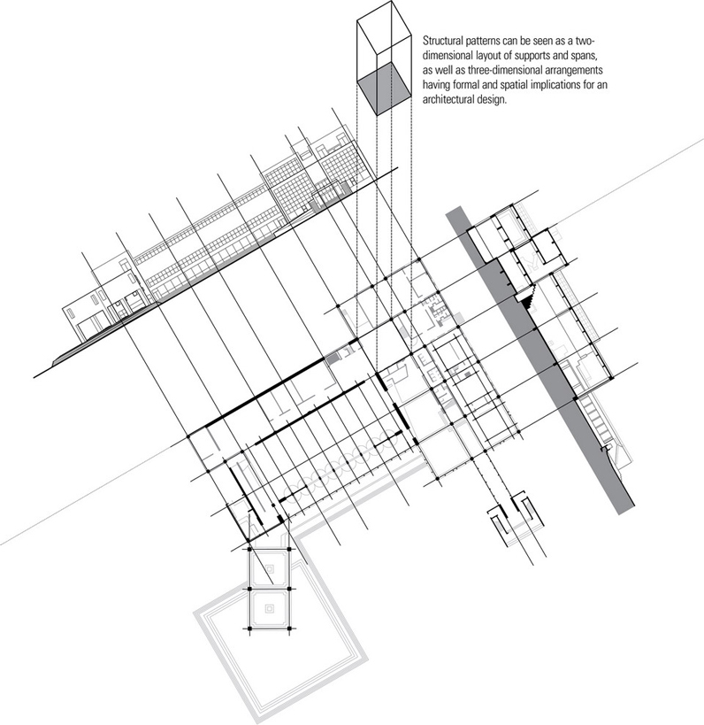
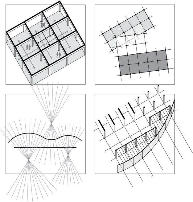
Structural patterns are three-dimensional compositions consisting of vertical supports, horizontal spanning systems, and lateral-force-resisting elements.
Pattern of Supports
- Vertical supporting planes
- Bearing walls
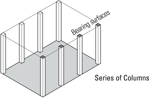
- Series of columns
- Column-and-beam frames
Pattern of Spanning Systems
- One-way spanning systems
- Two-way spanning systems
Pattern of Lateral-Force-Resisting Elements
See Chapter 5.
- Braced frames
- Moment-resisting frames
- Shear walls
- Horizontal diaphragms
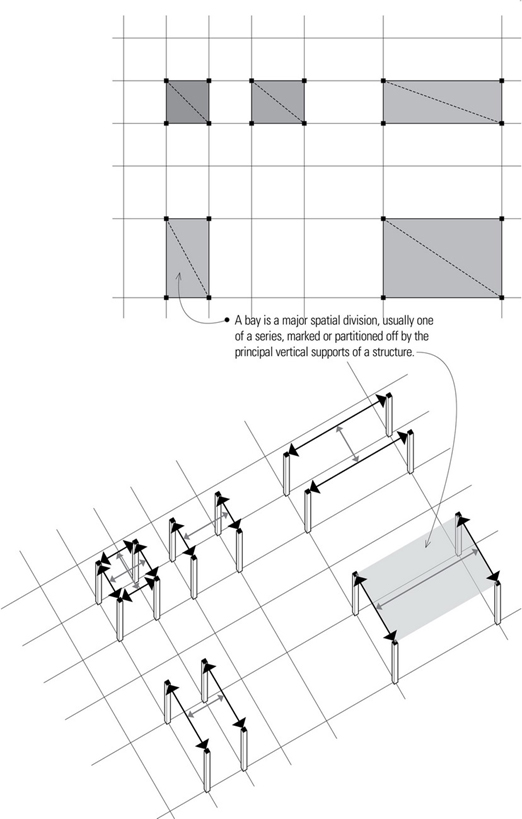
Structural Units
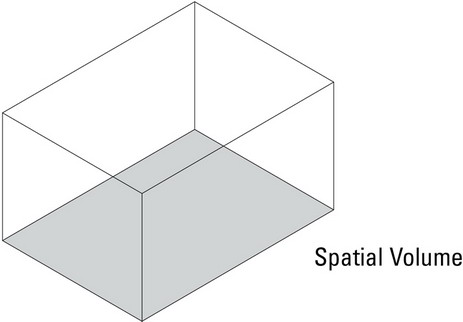
A structural unit is a discrete assembly of structural members capable of forming or marking the boundaries of a single spatial volume. There are several fundamental ways to define a single volume of space.
Support Options
Two columns supporting a beam or girder create an open framework that both separates and unites adjacent spaces. Any enclosure for physical shelter and visual privacy requires the erection of a nonbearing wall, which can either be supported by the structural frame or be self-supporting.
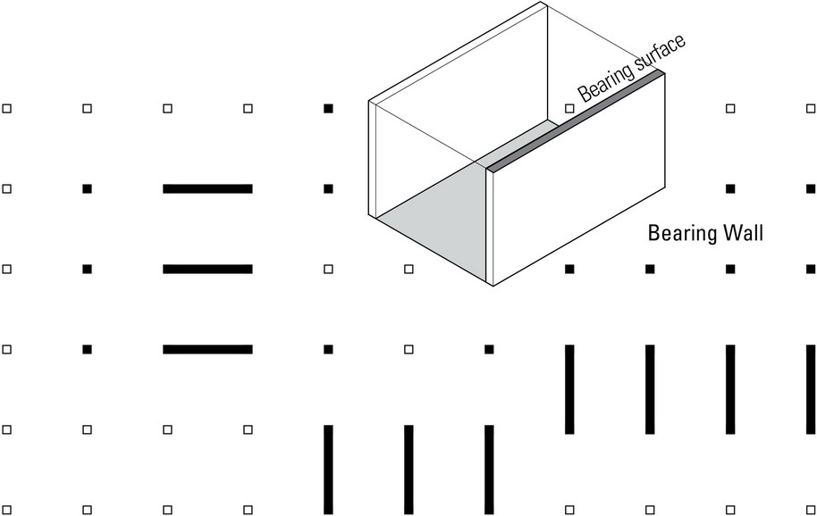
Columns support concentrated loads. As the number of columns increases and the column spacing decreases, the supporting plane becomes more solid than void and approaches the character of a bearing wall, which support distributed loads.
A bearing wall provides support as well as divides a field into separate and distinct spaces. Any opening required to relate the spaces on either side of the wall tends to weaken its structural integrity.
Both column-and-beam frames and bearing walls can be used in combination to develop any number of spatial compositions.

Spanning Options
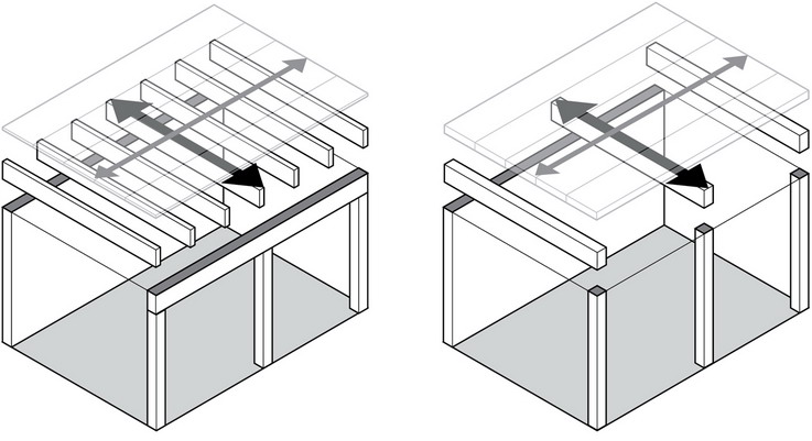
Creating a spatial volume requires a minimum of two vertically oriented support planes, be they column-and-beam frames, bearing walls, or a combination thereof. To provide shelter against the vagaries of weather as well as a sense of enclosure, some sort of spanning system is required to bridge the space between the support systems. In looking at the fundamental ways of spanning the space between two support planes, we must consider both the way applied forces are distributed to the supporting planes as well as the form of the spanning system.
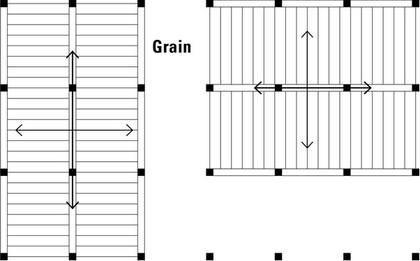
One-Way Spanning Systems
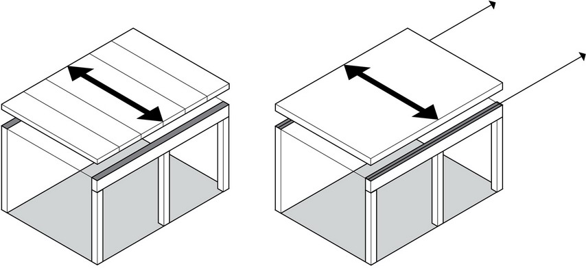
Whether the spanning system transfers and distributes applied forces in one or two (or even multiple) directions will determine the pattern of supports required. As the name implies, one-way systems transfer applied forces to a pair of more or less parallel supporting planes. This configuration naturally leaves two sides of the spatial unit open to adjacent spaces, giving it a strong directional quality.
Two-Way Spanning Systems
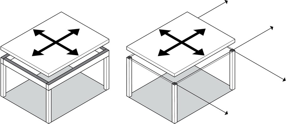
On the other hand, two-way systems transfer applied forces in two directions, requiring two sets of supporting planes or columns, more or less perpendicular to each other and the direction of transfer of forces.
In determining whether to use one-way or two-way systems, consideration must be given to a number of variables:
- Dimensions, scale, and proportions of structural bay
- Structural materials employed
- Depth of construction assembly
For more detailed information, see Chapters 3 and 4.
Assembling Structural Units
Because most buildings consist of more than a single, solitary space, the structural system must be able to accommodate a number of spaces of varying sizes, uses, relationships, and orientations. To do this, we assemble structural units into a larger holistic pattern that is necessarily related to how spaces are organized in a building and the nature of the building’s form and composition.
Because continuity is always a desirable structural condition, it is usually sensible to extend structural units along major support lines and span directions to form a three-dimensional grid. If it is necessary to accommodate spaces of exceptional shape or size, a structural grid can be adapted by distorting, deforming, or enlarging certain bays. Even when a single structural unit or assembly encompasses all of a building’s spaces, the spaces themselves must be structured and supported as units or compositional entities.
Structural Grids
A grid is a pattern of straight lines, usually equally spaced and intersecting at right angles, that serves as a reference for locating points on a map or plan. In architectural design, a grid is often used as an ordering device not only for locating but also for regulating the major elements of a plan. When we speak of a structural grid, therefore, we are referring specifically to a system of lines and points for locating and regulating the position of major structural elements, such as columns and bearing walls.

STRUCTURAL GRIDS
- The supports for two-way spanning systems establish two sets of parallel lines, usually intersecting at right angles.

- Even though a grid is primarily a plan device, it can be extended into the third dimension to regulate the height and location of floor and roof structures.
In developing a structural grid for a building concept, there are important grid characteristics that must be considered for their impact on the architectural idea, the accommodation of program activities, as well as the design of the structure.
Proportions
The proportions of the structural bays influence, and may limit, the material and structural choices of the horizontal spanning systems. While one-way systems are flexible and can span in either direction of either square or rectangular structural bays, two-way systems are best used to span square or nearly square bays.
Dimensions
The dimensions of the structural bays obviously impact both the direction and length of the horizontal spans.
- Direction of spans
The direction of horizontal spans, as determined by the location and orientation of the vertical supporting planes, affects the nature of the spatial composition, the qualities of the spaces defined, and to some extent, the economics of construction. - Span lengths
The spacing of the vertical supporting planes determines the length of the horizontal spans, which, in turn, affects the choice of materials and the type of spanning system employed. The greater the span, the deeper the spanning system will have to be.
Scale
In design, scale refers to the proportionate size or extent of an element or composition when judged in relation to some norm or standard. We use such terms as large-scale, small-scale, fine and coarse, to describe how we perceive or judge the relative sizes of things. In developing a structural grid, we can refer to its scale as well, judging the relative fineness or coarseness of the dimensions and proportions of the bays against what we might consider to be normal. The scale of a structural grid is related to:
- the type of human activity to be accommodated;
- the efficient span range for a particular spanning system; and
- the nature of the foundation soil of the building site.
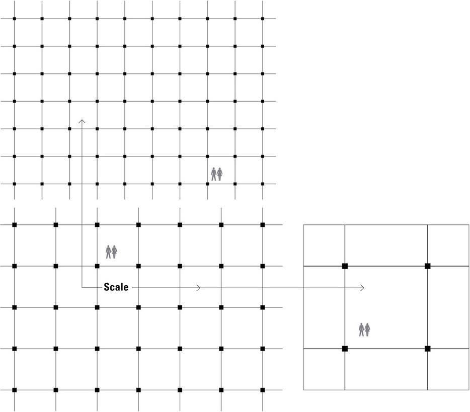
Another aspect of scale is the relative sizes of the members used. Some structures can be seen to be concentrated in nature due to their use of relatively large members carrying concentrated loads. On the other hand, there are some structures that use a multiplicity of small members that distribute their loads among a large number of relatively small members.
A final attribute of some structural systems is its grain, as determined by the direction, size, and arrangement of its spanning elements.
Spatial Fit
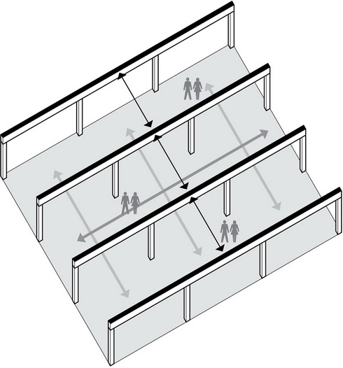
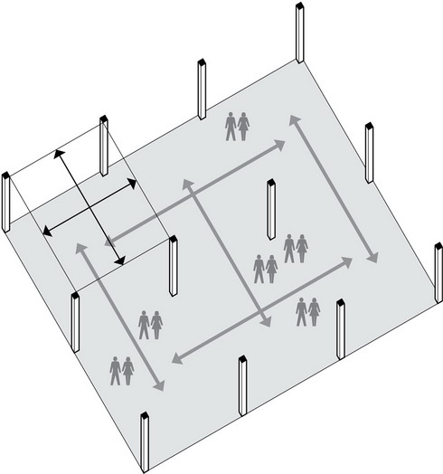
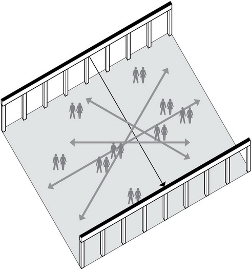
The nature, pattern, and scale of vertical supports suggested by a structural grid not only influence the type of spanning system used but also the arrangement of vertical supports should accommodate the intended patterns and scale of human activity. At a minimum, the vertical support pattern should not limit the usefulness of a space nor constrain its intended activities.
Those activities requiring large clear spans will often dictate the structural approach, but smaller-scale activities can usually be accommodated by a variety of structural approaches. Illustrated on this and the facing page are various types and scales of structural patterns and the pattern and scale of human activity each might be able to accommodate.
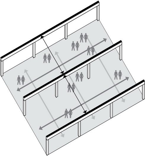
One-way spans
Bearing-wall supports
- If walls are necessary from a functional point of view, it might make sense to use them as loadbearing elements.
One-way spans
Beam-and-column supports
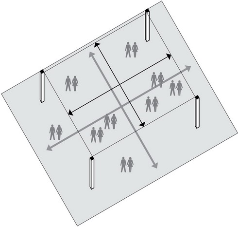
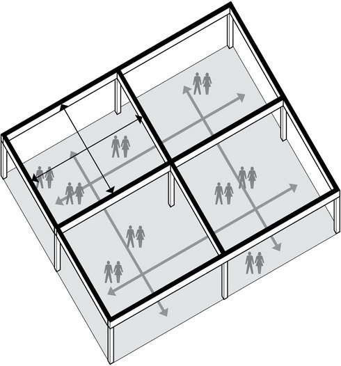
Two-way spans
Beam-and-column supports
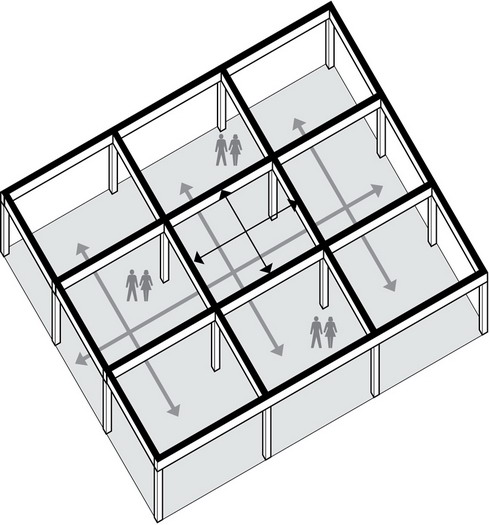
- A grid of columns offers flexibility, gives rise to multiple readings of spatial volumes, and establishes a rhythm and scale for reading the spatial dimensions.
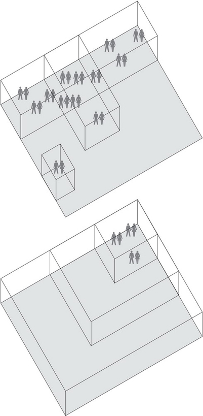
Two-way flat plate
Column supports
Two-way flat plate
Column supports
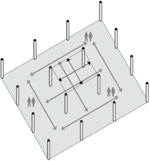
Two-way flat slab or space frame
Column supports
One-way spans
Beam-and-column supports
Two-way spans
Beam-and-column supports
One-way long spans
See Chapter 6.
REGULAR GRIDS
Regular grids define equal spans, allow the use of repetitive structural elements, and offer the efficiency of structural continuity across a number of bays. While regular grids cannot be considered the norm, they do provide a useful way to begin thinking about the structural implications of various grid patterns.
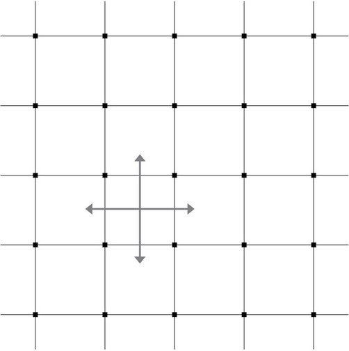
Square Grids
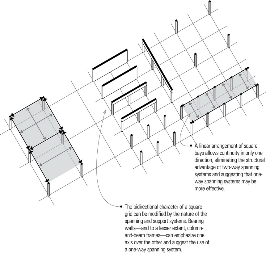
A single square bay can be spanned with either a one-way or two-way system. However, when multiple square bays extend across the field of a square grid, the structural advantage of continuity in two directions suggests the use of concrete two-way spanning systems is appropriate, particularly for small to medium span ranges.
It should be noted that while two-way structural action requires square or very nearly square bays, square bays do not always have to be spanned with two-way systems. For example, a linear arrangement of square bays allows continuity in only one direction, eliminating the structural advantage of two-way spanning systems and suggesting that one-way spanning systems may be more effective than two-way systems. Also, as a square bay grows beyond 60 feet (18 m), more one-way systems and fewer two-way systems become available.
- A single square bay can be spanned with either a one-way or two-way system.
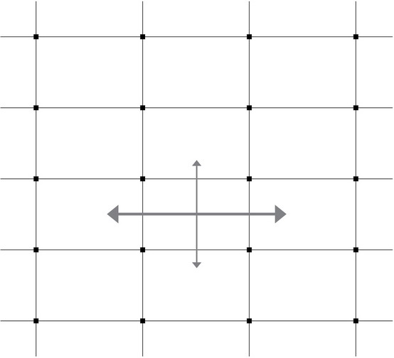
Rectangular Grids
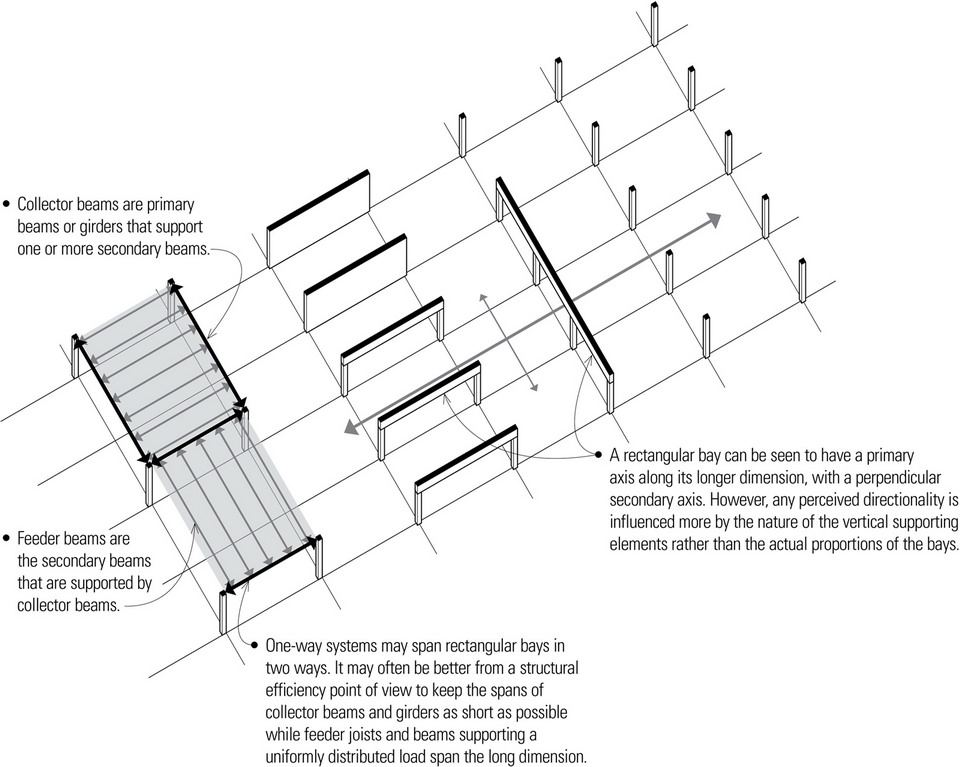
The bays of a rectangular grid usually lead to the use of one-way spanning systems, especially when one horizontal dimension of the bay dominates the other. The fundamental question is how to arrange the spanning elements. It is not always easy to determine in which direction the primary structural elements should span. It may often be better from a structural efficiency point of view to keep the spans of major beams and girders as short as possible and to span the long dimension of a rectangular bay with repetitive members supporting a uniformly distributed load.
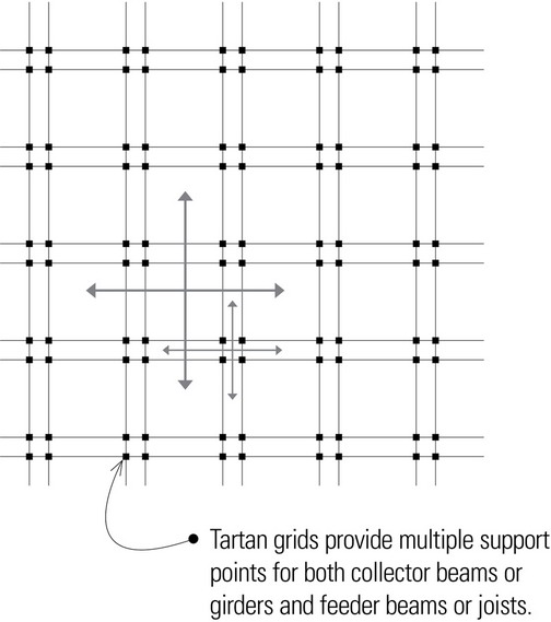
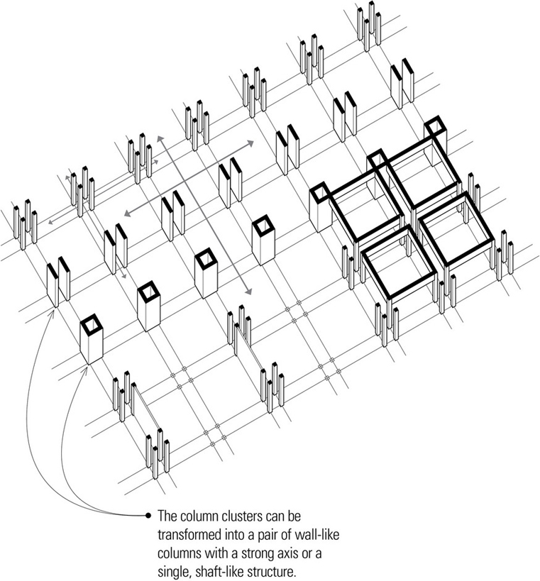
Tartan Grids
Both square and rectangular grids may be modified in a number of ways to respond to programmatic needs or contextual requirements. One of these is to offset two parallel grids to produce a tartan or plaid pattern of supports. The resulting interstitial or intervening spaces can be used to mediate between larger spaces, define paths of movement, or house mechanical systems.
While the tartan grid illustrated here is based on the square, rectangular tartan grids are also feasible. In either case, the decision to use one-way or two-way spanning systems depends on the bay proportions, as discussed on page 46.
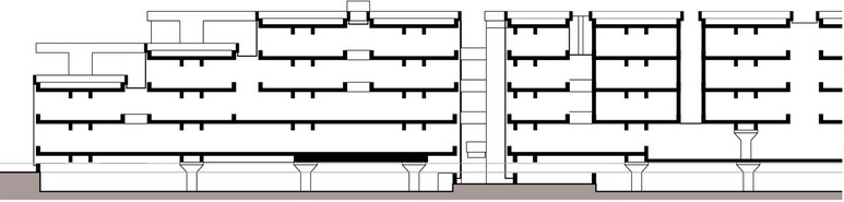
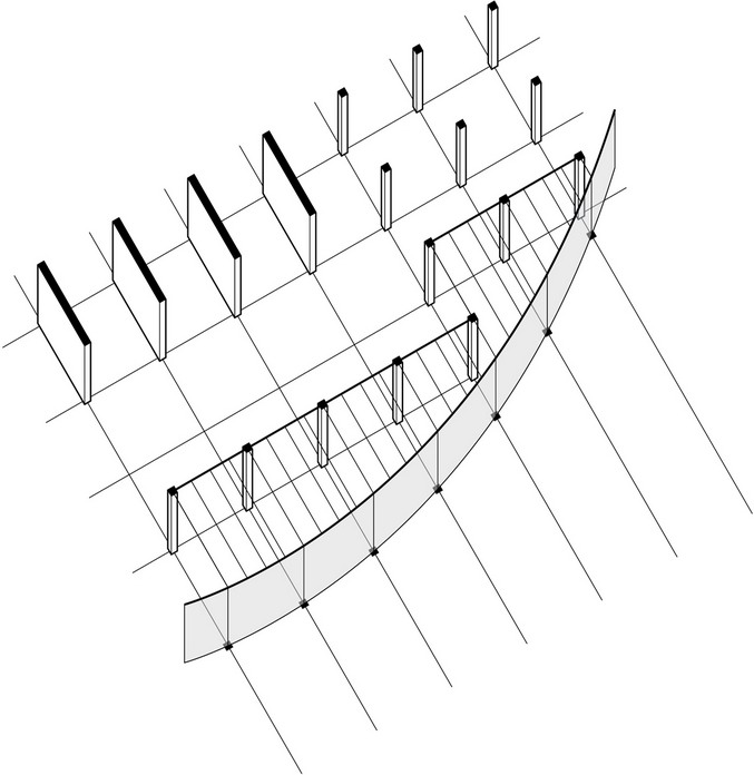
- Partial plan and section: Centraal Beheer Insurance Offices, Apeldoorn, Netherlands, 1967–1972, Herman Hertzberger
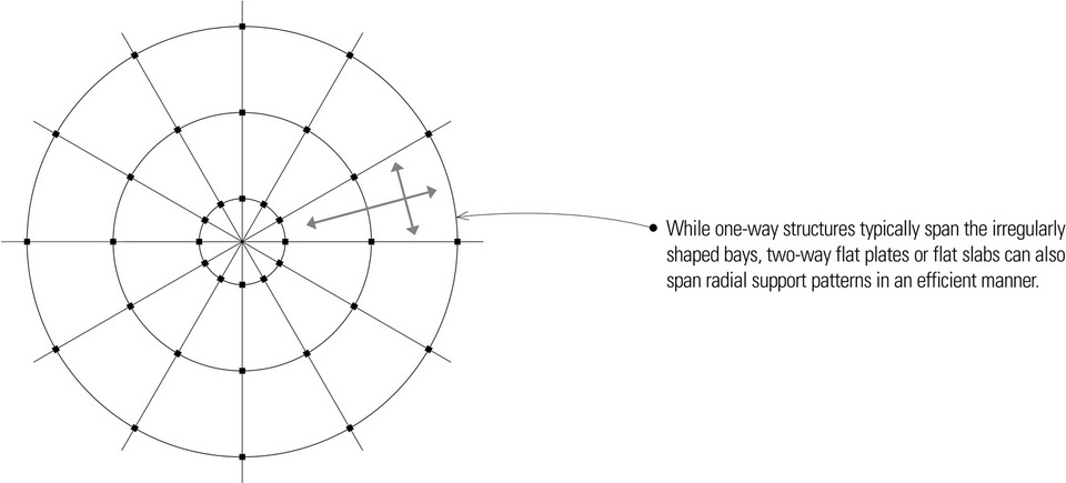
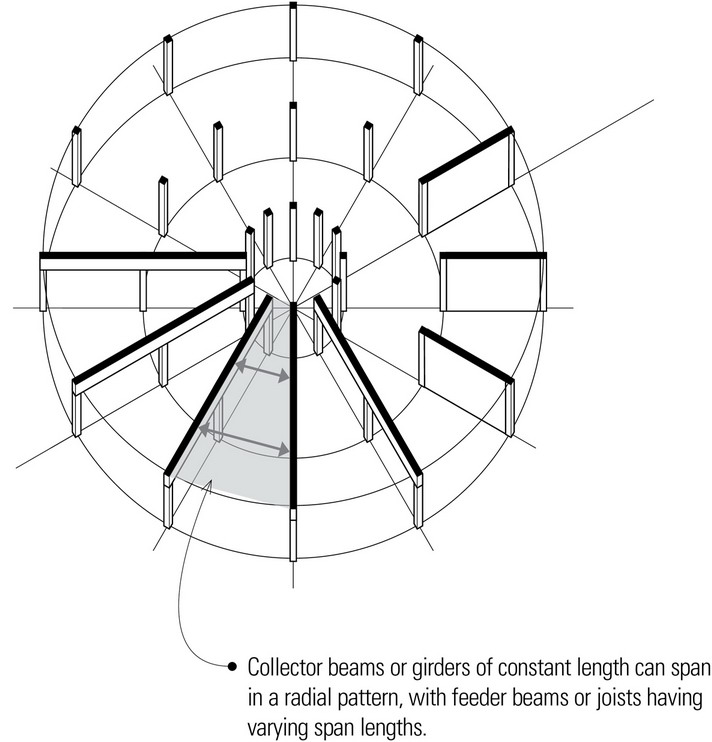
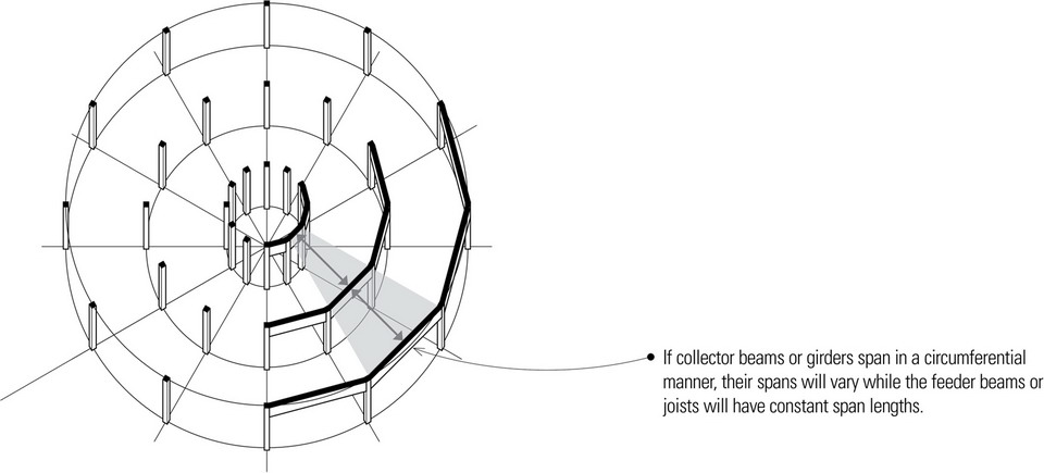
Radial Grids
Radial grids consist of vertical supports arranged in a radial pattern about a real or implied center. The direction of span is influenced by the support spacing, measured both radially and circumferentially.
IRREGULAR GRIDS
Modifying Grids
Square, rectangular, and tartan grids are all regular in the sense that they consist of regularly recurring elements regulated by orthogonal spatial relationships. They are capable of growth in a predictable manner, and even if one or more elements is missing, the pattern of the whole remains recognizable. Even radial grids have recurring relationships defined by their circular geometry.
In architectural design, grids are powerful organizing devices. It should be noted, however, that regular grids are only generalized patterns that can be modified and made specific in response to circumstances of program, site, and materials. The objective is to develop a grid that integrates form, space, and structure into a cohesive whole.
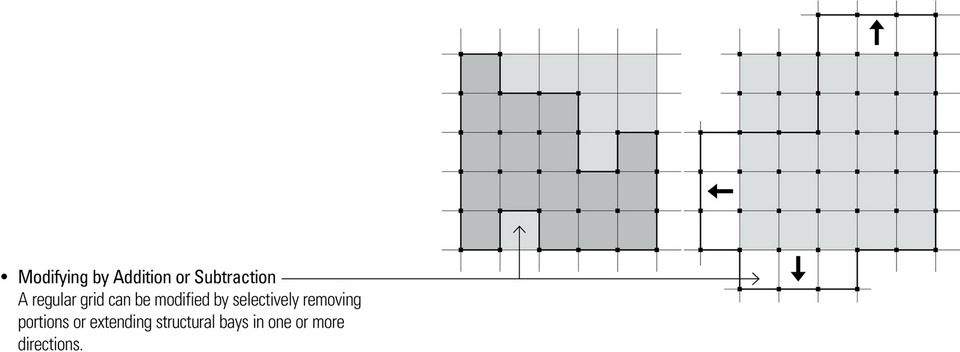
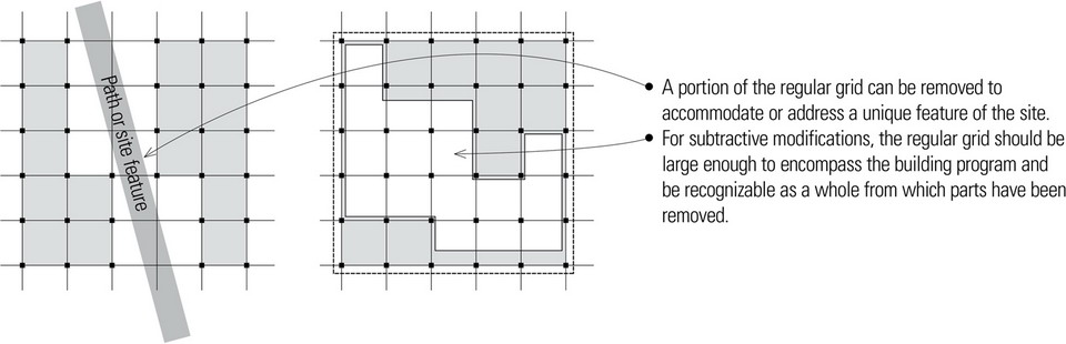
Modifying by Addition or Subtraction
Regular grids can be extended horizontally and vertically to form new compositions of forms and spaces. Such additive compositions can be used to express growth, establish a linear sequence of spaces, or to collect a number of secondary spaces about a major or parent form.

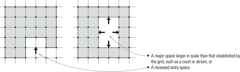
Subtractive modifications result from the selective removal of a portion of a regular grid. This subtractive process may occur to create:
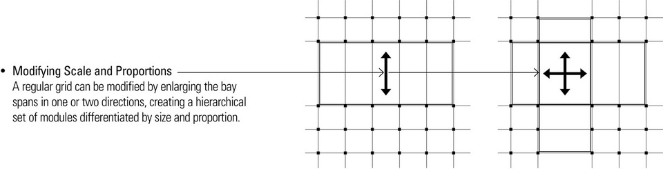
Modifying Proportions
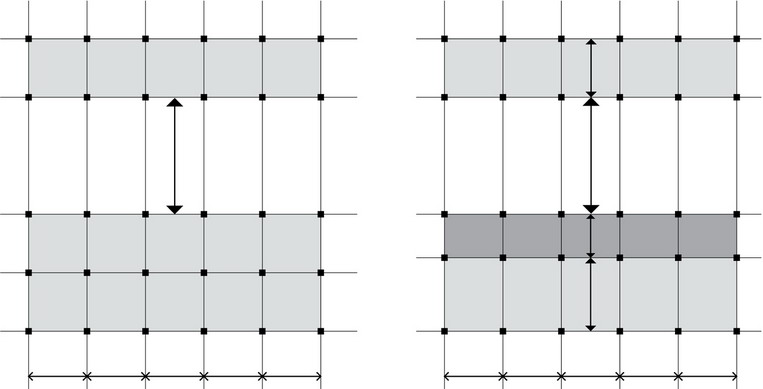
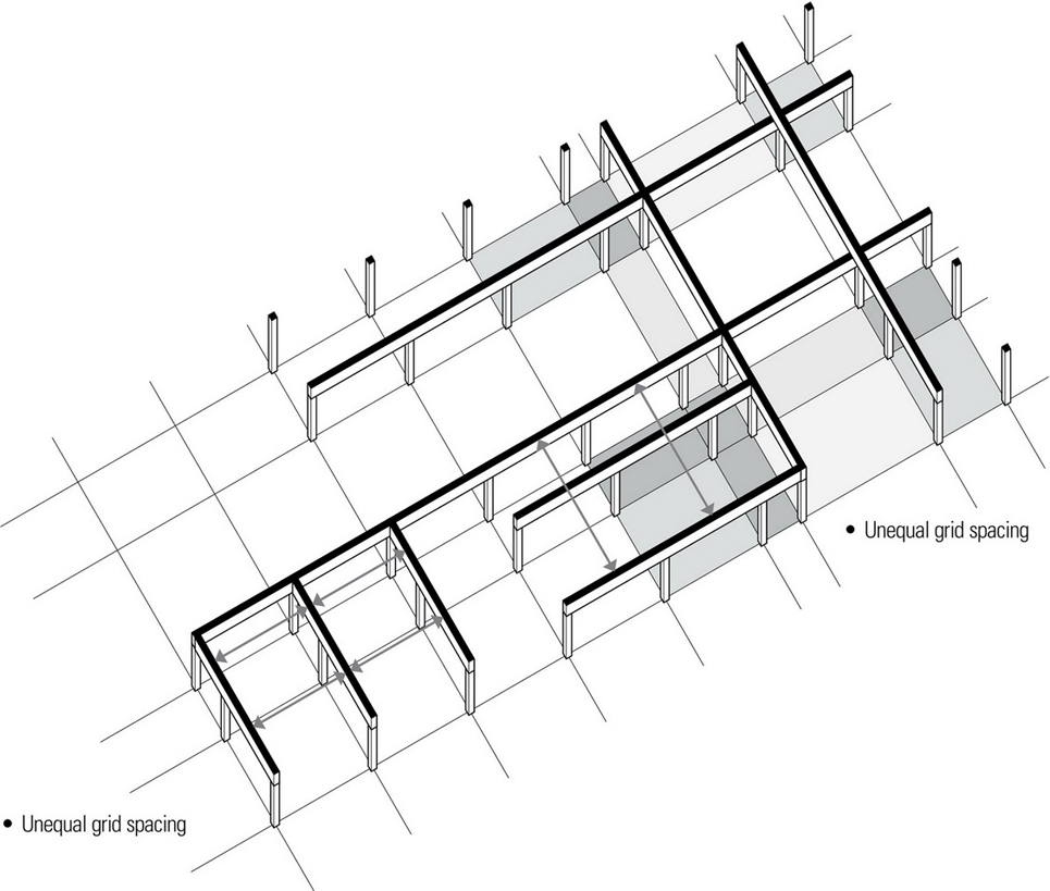
To accommodate the specific dimensional requirements of spaces and functions, a grid can be made irregular in one or two directions, creating a hierarchical set of modules differentiated by size, scale, and proportion.
When the structural grid is irregular in only one direction, the collector beams or girders can span uneven bay lengths while the feeder beams or joists retain constant spans. In some cases, it might be more economical to have the collector beams or girders have equal spans while the feeder beams or joists have varying span lengths. In either case, the unequal spans will result in the spanning systems having different depths.
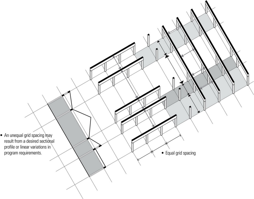
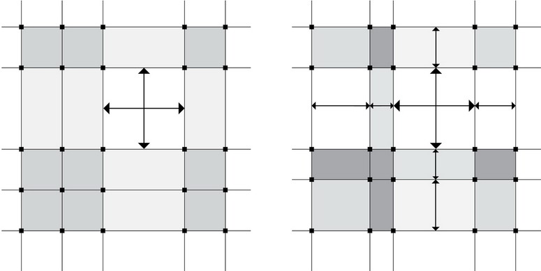
The structural grid can be made irregular in two directions to achieve a tighter fit between structure, space, and function. In this case, the direction of spanning elements will vary along with the proportion of the structural bays. As the structural bays vary in proportion, it is important to understand that the tributary load areas for both the spanning members and vertical supports will vary as well.
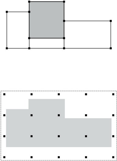
Accommodating Large-Scale Spaces
When spaces are much larger in scale than those required for typical uses, such as for auditoriums and gymnasiums, they can disrupt the normal rhythm of a structural grid and the increased spans and resulting loads—both gravity and lateral—on vertical supports require special consideration.
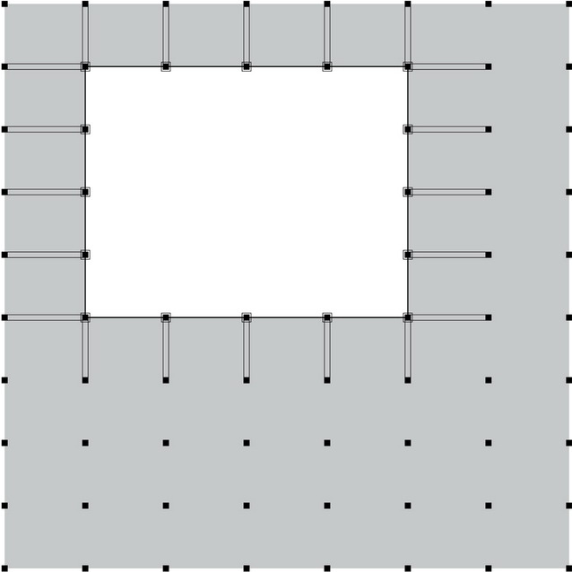
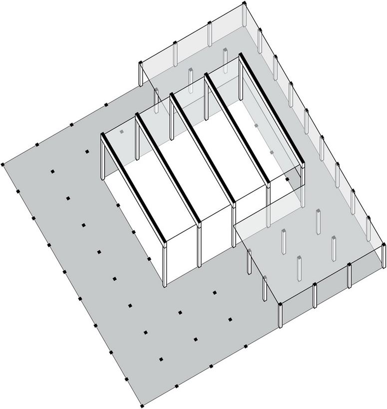
Larger-than-normal spaces may be embedded in the structural grid, be separate but attached to the grid, or be large enough to encompass support functions into its volume. In the first two instances, it is usually best to have the vertical supports of the large-scale space be equal to or some multiple of the regular support grid. In this way, horizontal continuity can be maintained throughout the structure.
- A large-scale space that is embedded within a grid can be supported and buttressed by the structure of the surrounding spaces. If the grid of the large space does not align with that of the surrounding spaces, then some sort of transitional structure would be necessary to accommodate the shift.
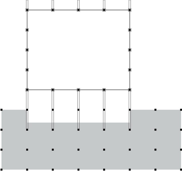
- The desired architectural expression may be that of a large-scale space that is separate from but connected to an adjacent structure. Articulating the large-scale space in this way can alleviate the difficulty that may arise when two different types of structural systems meet or when two structural grids are misaligned. In either case, a third structural system would be required to make the transition.
- For the possible sectional relationships of large-scale spaces to adjacent spaces, see Chapter 4.
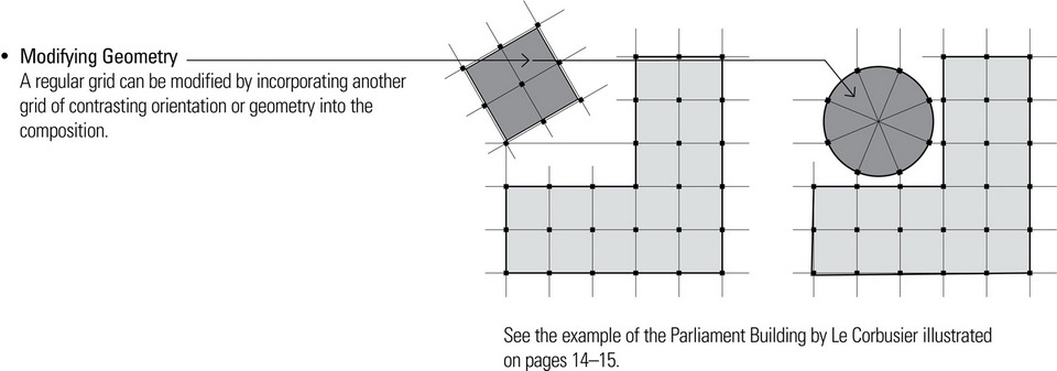
- See the example of the Parliament Building by Le Corbusier.
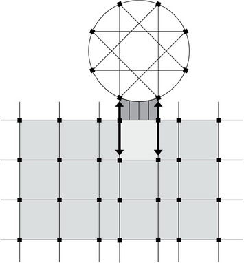
Contrasting Geometries
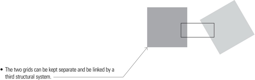
A regular grid can meet a grid of contrasting geometry to reflect differing requirements of interior space and exterior form or to express the importance of a form or space within its context. Whenever this occurs, there are three ways in which to handle the geometric contrast.
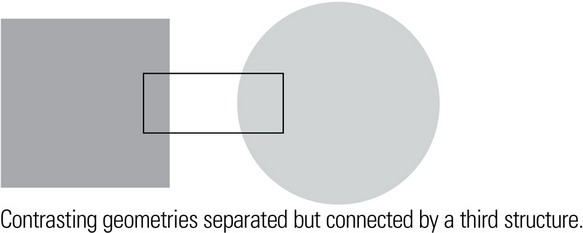
- The two contrasting geometries can be kept separate and be linked by a third structural system.
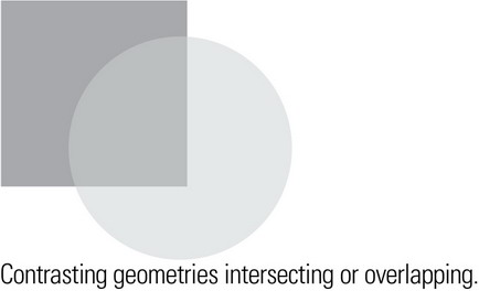
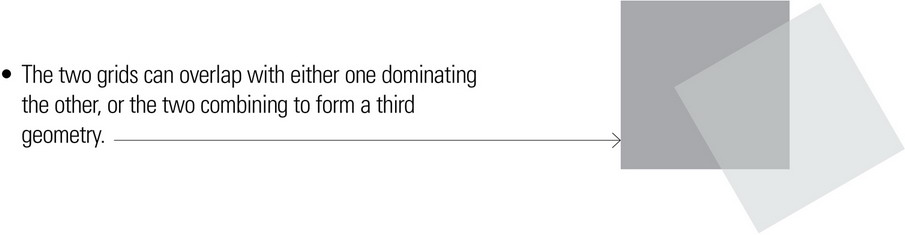
- The two contrasting geometries can overlap with either one dominating the other, or the two combining to form a third geometry.
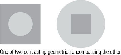
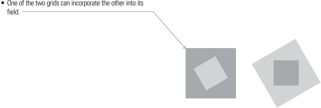
- One of the two contrasting geometries can incorporate the other into its field.
The transitional or interstitial space formed by the intersection of two contrasting geometries can, if large or unique enough, begin to attain an importance or significance of its own.
In the latter two cases, the resulting irregular or nonuniform layout of vertical supports and varying span lengths makes it difficult to use repetitive or modular structural members. See Accommodating Irregular Shapes for transitional patterns to mediate between straight and curvilinear structures. for transitional patterns to mediate between straight and curvilinear structures.
- Contrasting geometries separated but linked
- Overlapping geometries
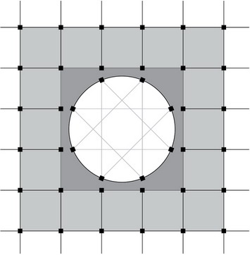
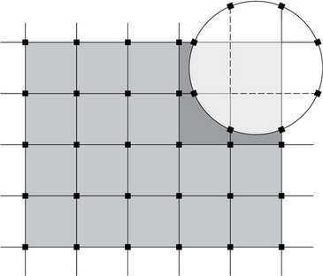
- Circular geometry embedded in a rectangular geometry
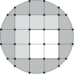
- Rectangular geometry embedded within a circular geometry
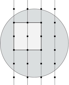
- Rectangular geometry within a circular geometry
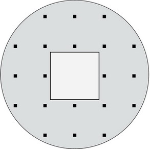
- Rectangular geometry within a circular geometry
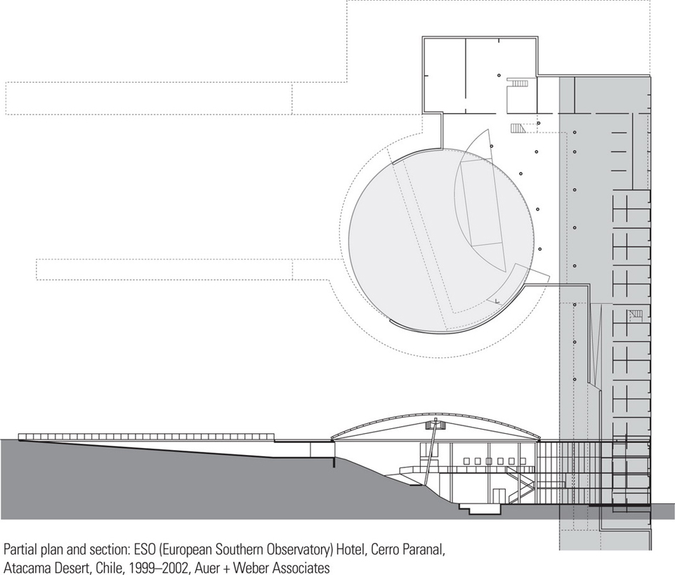
The examples that follow illustrate ways in which two contrasting geometries—the circular and the rectangular—can be related. The Bibliotheca Alexandrina exhibits a rectangular structural grid within a circular form. The Lister County Courthouse embraces the circular courtroom space partly within the boundaries of a rectangular form. The large, sheltered circular courtyard of the ESO Hotel is separate from but linked by a terrace to the linear block of accommodations.


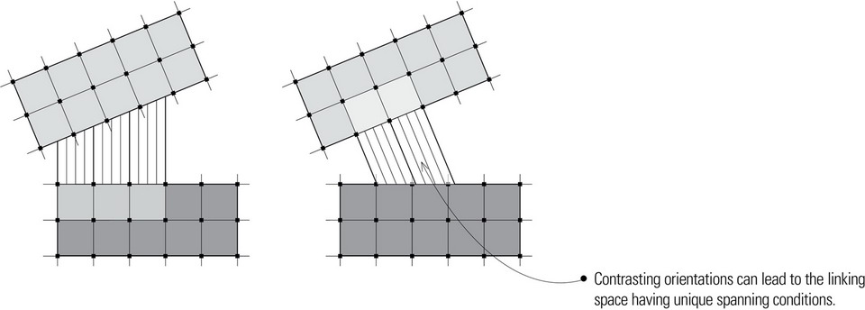
Contrasting Orientation
Just as two structural grids may have contrasting geometries, they also might have differing orientations to address unique features of a site, accommodate an existing pattern of movement, or express contrasting forms or functions within a single composition. And as in the case of contrasting geometries, there are three ways in which to resolve how the two grids that differ in orientation resolve into a single structure.
The transitional or interstitial space formed by the intersection of two geometries having contrasting orientations can, if large or unique enough, begin to attain an importance or significance of its own.
In the latter two cases, the resulting irregular or nonuniform layout of vertical supports and varying span lengths make it difficult to use repetitive or modular structural members. See the following page for transitional patterns to mediate between grids having differing orientations.
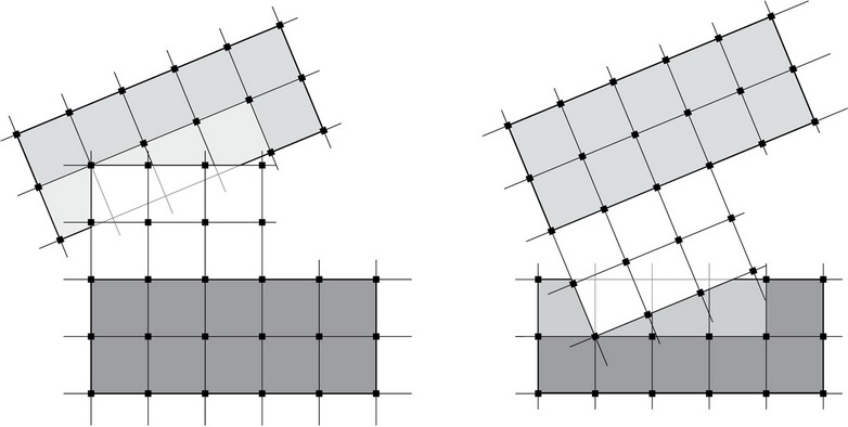
The transitional link between two geometric orientations may reflect either one of the orientations or neither of them. If the linking space conforms to one of the orientations, the contrasting orientation will tend to be emphasized.
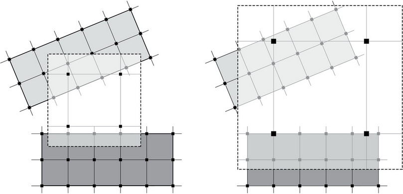
When two grids of contrasting orientation overlap, one will tend to dominate the other. The ascendency of one grid can be further emphasized by a change in vertical scale. Strong structural and architectural emphasis is placed on the exceptional spaces where one can experience both geometries.
Another way of treating differing orientations is to unify both parts by gathering them under a third dominant structural form. Like the examples above, emphasis occurs at the exceptional condition of two different structural systems are juxtaposed.
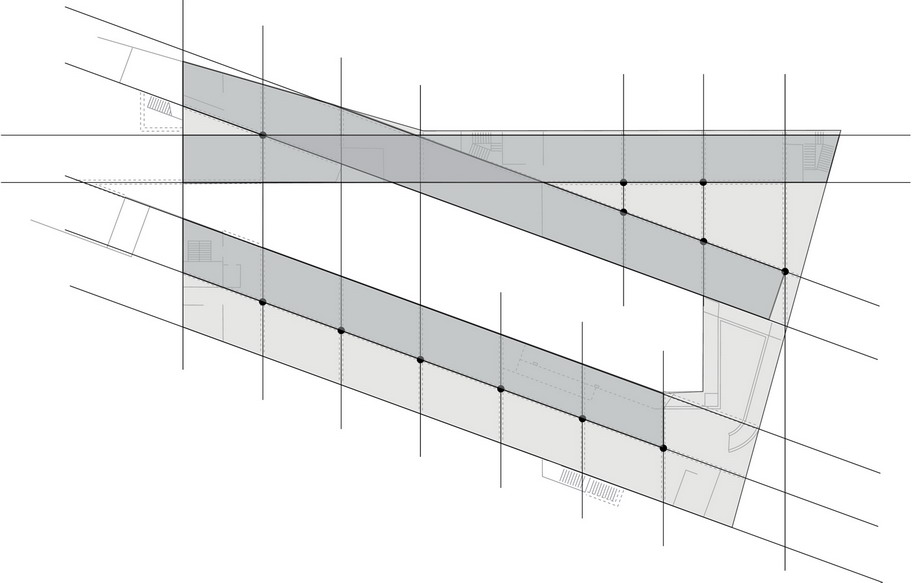
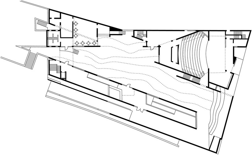
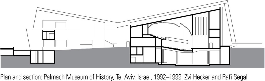
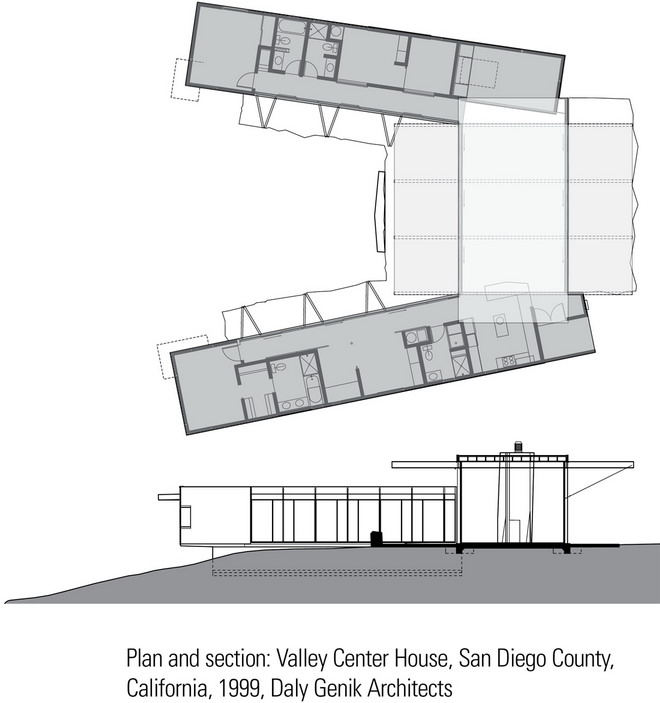
The examples on this and the previous page illustrate several ways in which contrasting orientations can be accommodated within a single composition.
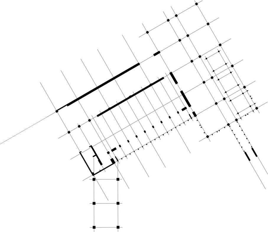
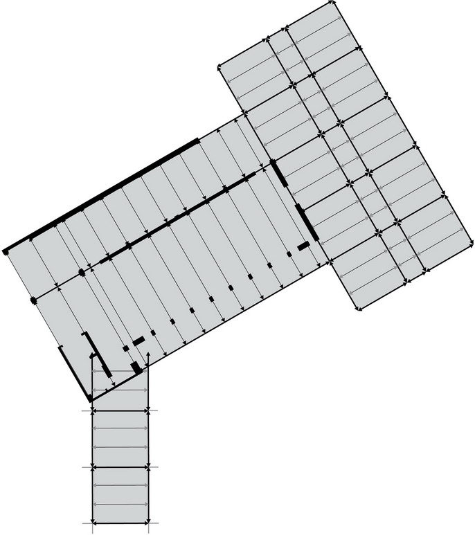
The Palmach Museum of History consists of three parts, two of which are skewed to preserve an existing cluster of trees and rocks and define an irregularly shaped courtyard. The structure of the Lois & Richard Rosenthal Center for Contemporary Art is based on a regular rectilinear grid but the columns have the shape of parallelograms to reflect the skewed geometry of the full-height, skylit atrium space housing the vertical system of stairways. The Valley Center House uses the main living room as a transitional structure that rises above to visually link the contrasting orientations of two wings.

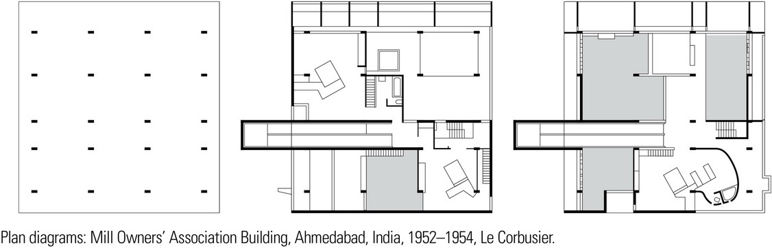
Accommodating Irregular Spaces
Design ideas are often generated not from the pattern of structural supports and spanning elements but rather from the desired ordering of program spaces and the formal qualities of the resulting composition. In a typical building program, there are usually requirements for various kinds of spaces. There may be requirements for spaces that are singular and unique in their function or significance to the building organization; others may be flexible in use and can be freely manipulated.

Discrete irregular spaces may be framed by the structure to conform with and reinforce the program requirements of the spatial volume.
This usually involves working back and forth between a structural concept and the program requirements for the space, searching for an appropriate fit between the structural strategy and the vision for the formal, aesthetic and performance qualities of the resulting spatial environment.
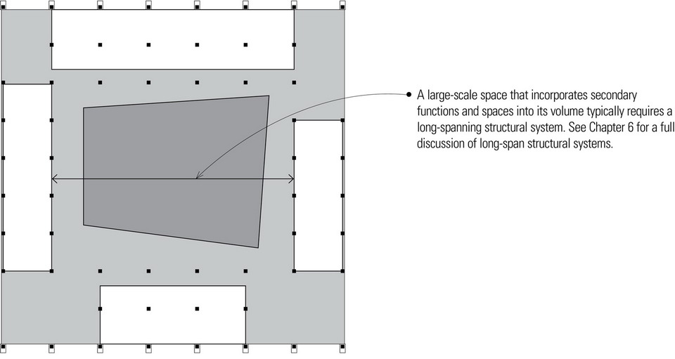
A discrete irregular space may also be developed as an independent structure with a separate structural system and geometry superimposed over the building as a whole. Although appropriate to accommodate the spatial requirements of such spaces as theaters, concert halls, and large galleries, this strategy typically requires long-span spanning systems. For a discussion of long-span structures, see Chapter 6.
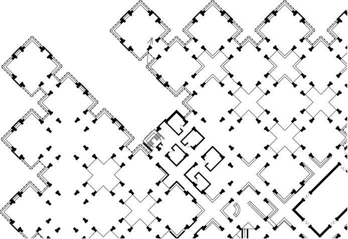
Accommodating Irregular Shapes
See plan and section of Centre Le Corbusier.
Accommodating Irregular Shapes
It is advisable to try to recognize the inherent geometry embedded in irregular plan shapes when attempting to develop a strategy for its structural system. Even the most irregular of plan shapes can often be dissected into parts which can be seen to be transformations of regular geometric shapes.
The manner in which an irregular shape or form might be constructed will often suggest logical options for a framing strategy. This may be as simple as using the center of an arc for a radial framing system or framing parallel or perpendicular to a significant wall or plane within an irregular geometry. Curves, especially, possess a number of properties for establishing the basis for a framing strategy. One might use the radius or center of an arc, a point that is tangent to the arc, or in the case of double curvatures, the inflection point where a change in curvature occurs. The approach one takes will depend on the design intent and how the structural strategy might reinforce the concept.
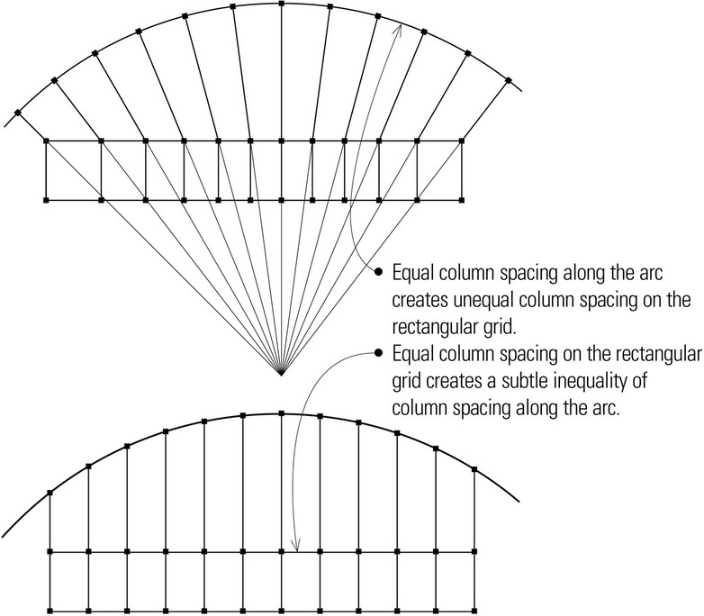
Although structural framing systems are usually developed in plan, consideration should also be given to the effect of the structure on the vertical aspects of a building—its elevations and the scale of its interior spaces. If column locations will be expressed in the facade, for example, the visible effect of a regular column spacing on a curving exterior wall plane should be considered.
Part of the challenge of structuring irregular plan shapes is to minimize the structural inefficiency that often results from the inevitable variations in span lengths.
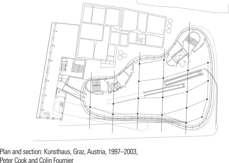
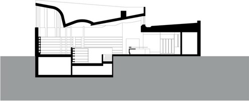
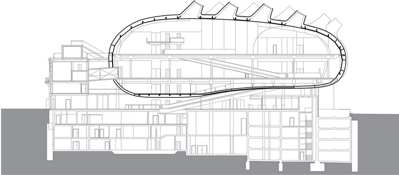
The following examples illustrate two ways in which irregular forms have been integrated into the rectilinear geometry of a composition. The bulbous form housing the exhibition spaces and related public facilities in the Kunsthaus is partly a response to an irregular site and the required fire-separation distance from existing adjacent buildings. It appears to float above the geometry of the structural grid that supports it.
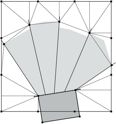
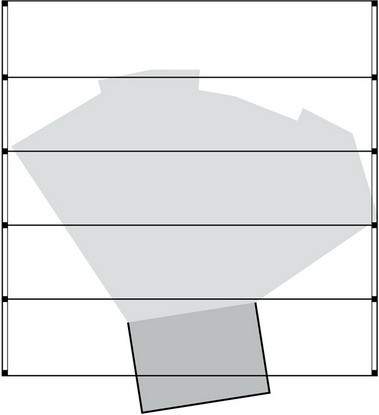
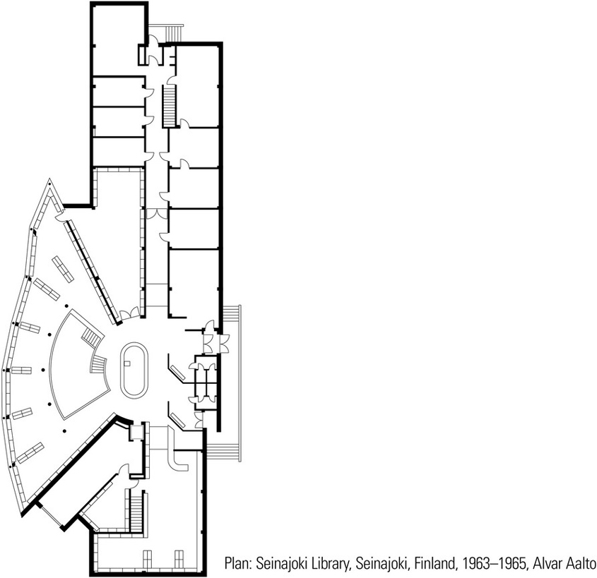
The significance of the main reading room of the Seinajoki Library is expressed in both plan and section by its fan-like shape, which is anchored at the circulation desk to the rectilinear geometry of the offices and support spaces.
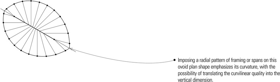
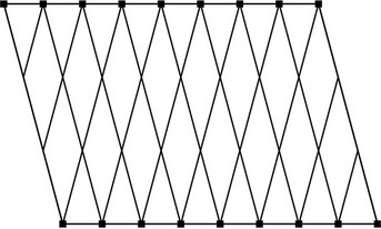
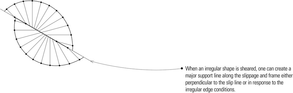
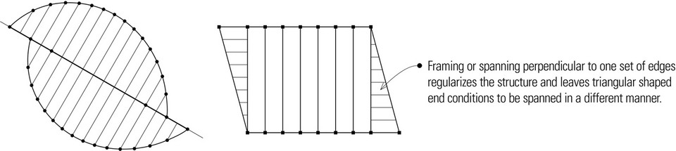
Plan shapes may evolve that do not conform to or incorporate a clear rectilinear or curvilinear geometry, such as ovoids and parallelograms. One approach is to select or create a significant edge or linear condition off of which one can orient the grid or framing pattern. These plan diagrams are just a few of the many possibilities that emerge.
- This parallelogram offers a choice of framing or spanning parallel to one set of edges or the other while maintaining a uniformity of span length.
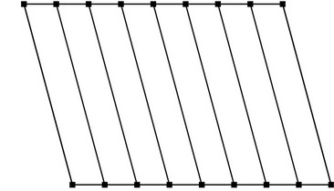
- Recognizing the geometry of the parallelogram can lead to a variety of lattice-type structures.
These plans show two ways in which irregular plan shapes can incorporate a regular grid pattern.
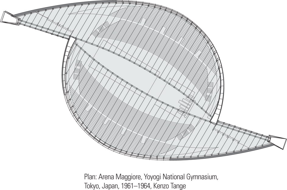
The dramatic sweep of the tensile roof structure of the Yoyogi National Gymnasium is created by prestressed cables suspended from two larger steel cables, which in turn are supported between two structural towers. From this central spine, the roof cables drape down and are anchored to curvilinear concrete bases. The plan view, however, shows the regularity of the cable spacing.
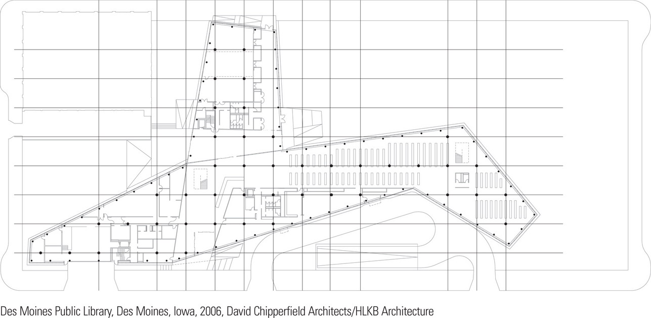
The angular, multifaceted nature of the Des Moines Public Library building belies the regularity of the structural grid of columns on the interior. Note how secondary columns define the boundaries of the building facades.
Accommodating Irregular Edge Conditions
Buildings may be shaped by the configuration of the site, the possibilities for view corridors and outlook, the edge conditions of streets and street frontages, or by the desire to preserve unique topographic features. Any of these conditions can lead to an irregular geometry that must be rationalized with the building program and the structural system devised to house it.
One strategy is to reduce the building form into orthogonal shapes with different orientations. This will often result in exceptional conditions that must be resolved at the intersections between the orthogonal parts of the composition. See pages 64–65.
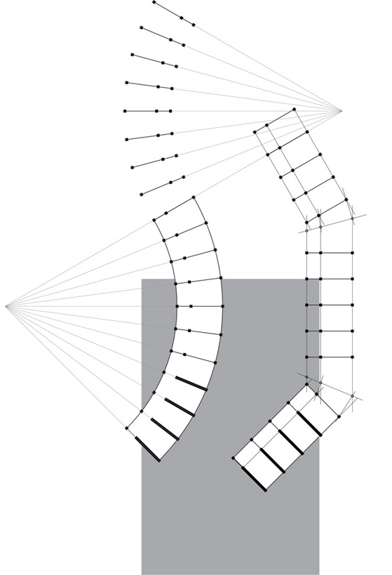
Another approach is to adapt a series of equivalent spatial units or formal elements to an irregular edge condition by bending the linear array along the path of the irregularity. The irregularity can be regularized by visualizing it as a series of curvatures and recognizing the center of radius for each arc segment as well as the points of inflection where changes of curvature occur.
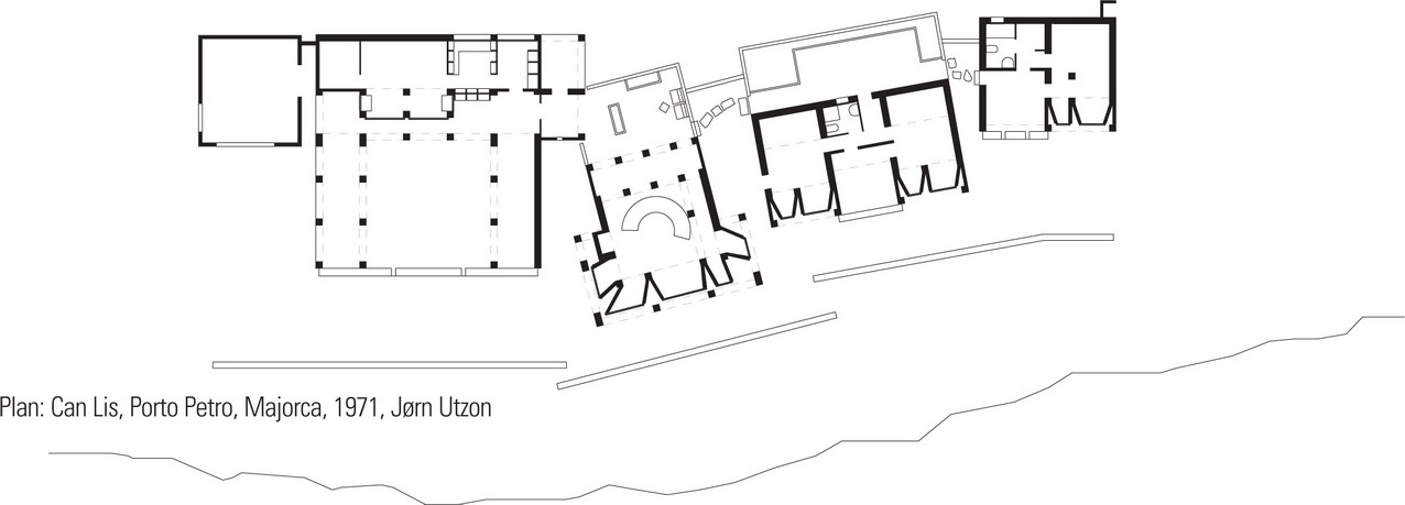
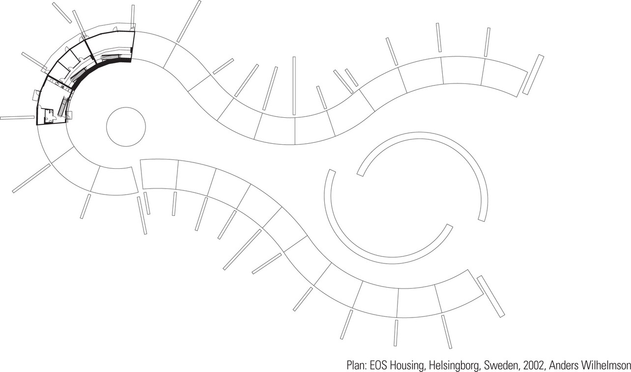
These projects show how we can respond to irregular edge conditions. Can Lis, perched high on the edge of a cliff overlooking the Mediterranean, appears to be a loose collection of small, vernacular buildings linked by a circulation spine. The individual nature of the forms or spaces allows each to be oriented independently of each other. The EOS Housing project, on the other hand, is a terrace housing scheme. The sinuous, continuous forms are generated by the radial geometry of the party walls that separate the individual housing units.
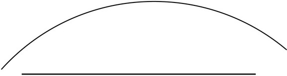
A classic duality in architectural design lies in the opposition between the straight and the curved. Reference has already been made to this opposition on page 70. Presented here are additional approaches to resolving the tension between a curved surface or plane and the rectilinear geometry of a regular structural grid. Each has implications on the design of the structural form as well as the quality of the interior spaces.
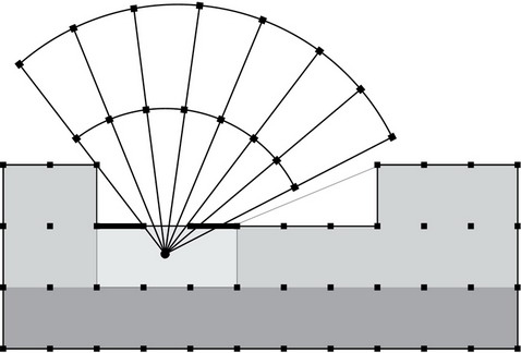
One could begin with the geometry that generated the curved surface or plane. This might suggest a framing or spanning pattern that reinforces the curvilinear edge to the space that is generated. The radial nature of the pattern would contrast strongly with the orthogonal grid, which could reinforce a distinction between two parts of the building program. The opposite approach would be to extend the orthogonal relationships established by the regular grid structure to the curved surface or plane.
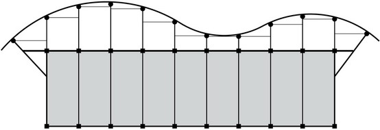
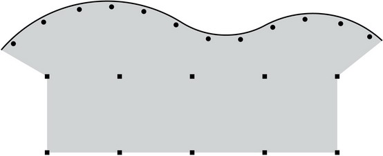
- In this plan diagram, the radial pattern reinforces the undulating nature of the space enclosed by the curvilinear surface or plane, which is reflected in the irregular spacing of the column supports in the rectangular portion of the structure.
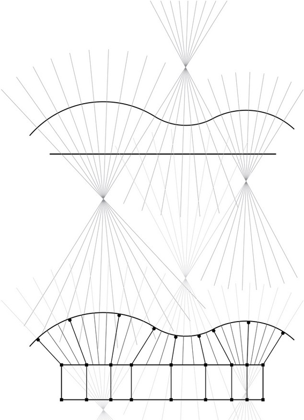
- Extending the orthogonal bay structure to the curvilinear surface or plane creates an irregular series of spaces that mediate between the straight and the curved and unifies the two edge conditions.
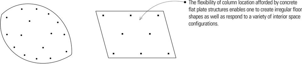
- The flexibility of column location afforded by concrete flat plate structures enables one to create irregular floor shapes as well as respond to a variety of interior space configurations.
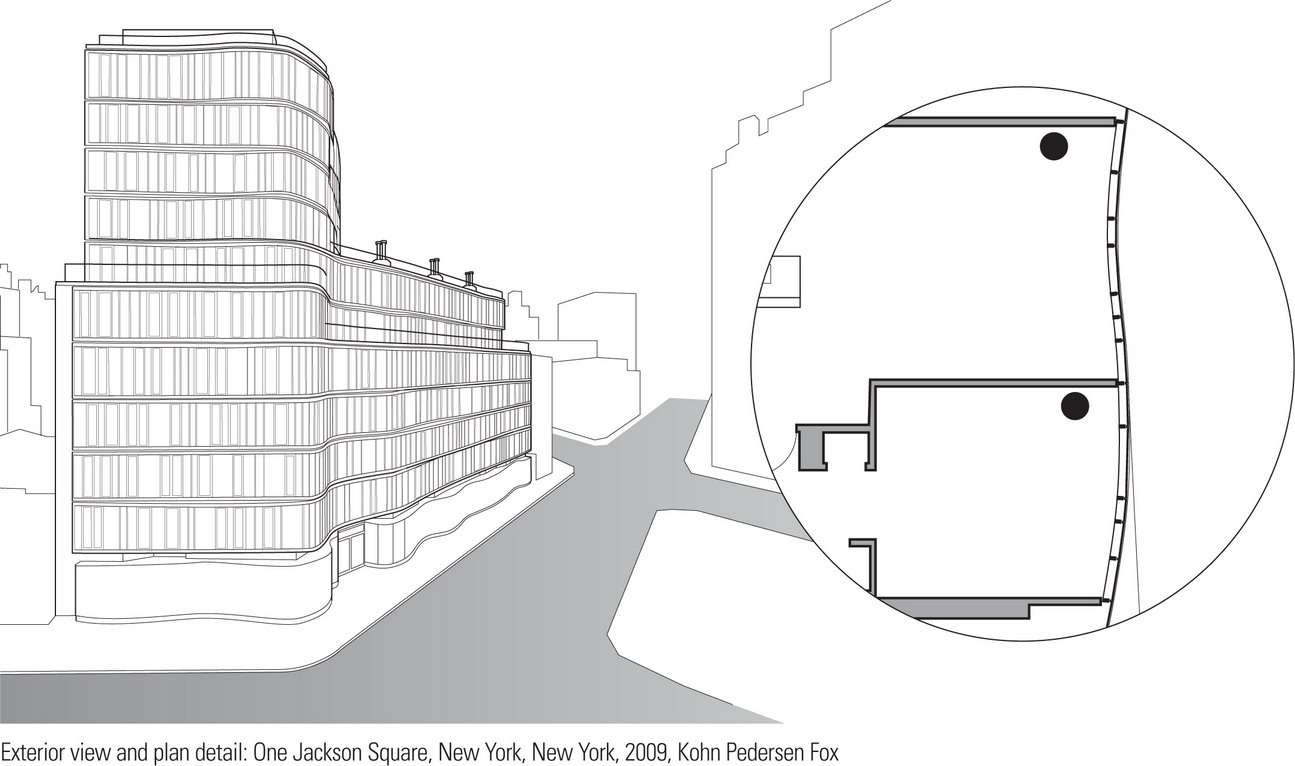
These two examples show how curvilinear curtain walls can be created. The irregular, site-assembled curtain wall panels of One Jackson Square are attached to the curvilinear perimeter of the overhanging concrete slabs. The slab edges had to be formed precisely so that the mullion joints of the curtain wall system would align properly. In a few of the units containing double-height spaces, a large beam replaced the slab edge as a means of support for the curtain wall.
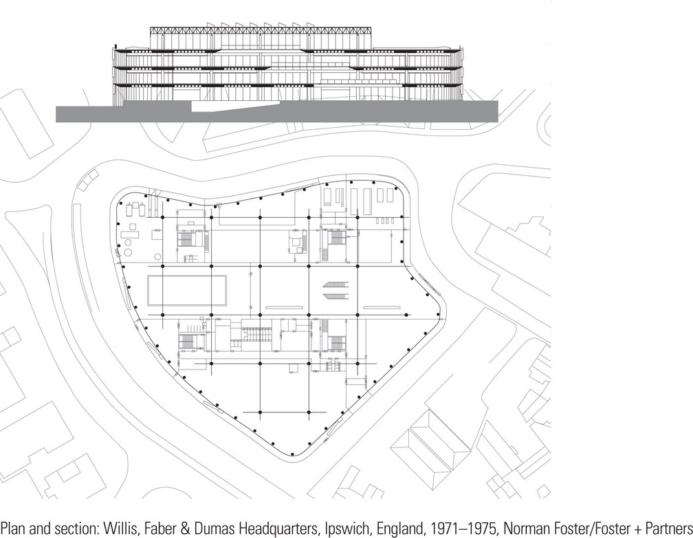
The central portion of Willis, Faber & Dumas Headquarters consists of a square grid of concrete columns spaced at 46-foot (14-m) centers while perimeter columns are set back from the curvilinear slab edges. Dark, solar-tinted glass panes are connected by corner patch fittings and silicone-jointed to form a three-story-high curtain wall, which is suspended from a perimeter edge beam at the roof level. Glass fins provide lateral bracing.
Sheared Grids
Two portions of a building may be adjacent to each other, each responding in its own way to programmatic or contextual requirements or constraints. Each may also require two different types of structural patterns that meet along a common line of support. Each may have similar structural patterns but one may slip or displace relative to the other. In these situations, differences between the parts may be expressed in the scale or grain of the respective structural patterns.

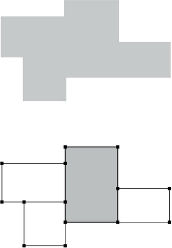
- When the scale and grain of two grids are similar, any differences can be resolved simply by selectively adding or subtracting bays. If there is an established grid structure, this will emphasize the plane along which the shift or shearing occurs.
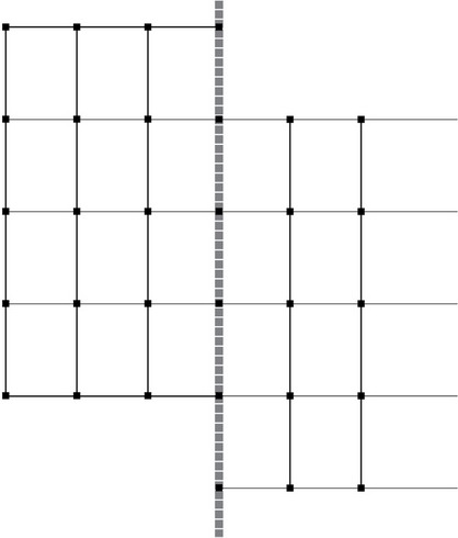
- A shearing of the grid can occur along a shift in spatial scale or grain. This may be accomplished using a common girder along the shear line. Because column spacings can vary along a bearing line, especially if beam spans are reasonably short, the positions of the columns supporting the girder can respond easily to local conditions.
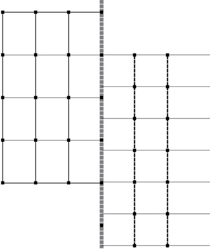
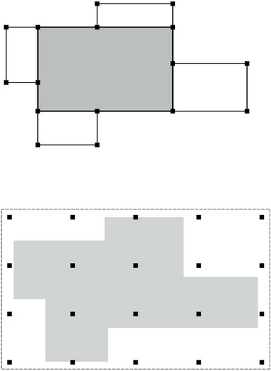
- Two structural patterns that differ in scale and grain can meet and align easier if the larger grid structure is some multiple of the smaller grid structure.
- If two primary grids that differ in scale, proportion, or grain cannot be resolved along a bearing line of columns and beams or girders, a third structure can be introduced to mediate between the two structures. Having a relatively short span, this mediating structure can often have a finer grain, which can help resolve the different spacings and support patterns of the two primary grids.
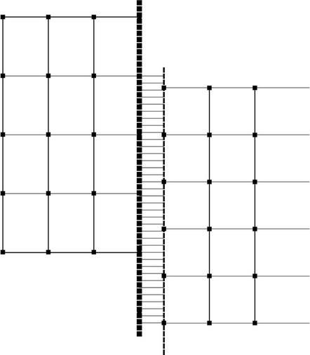
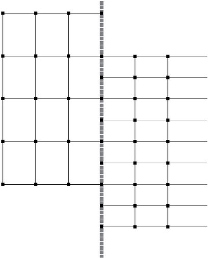
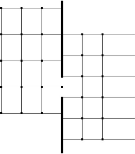
- If adjacent occupancies can tolerate the degree of separation afforded by a bearing wall, the wall itself can serve to join two contrasting structural grids. The nature of a bearing wall divides a space into two distinct fields. Any penetration through the bearing wall can take on additional significance as a portal or threshold between the two elements.
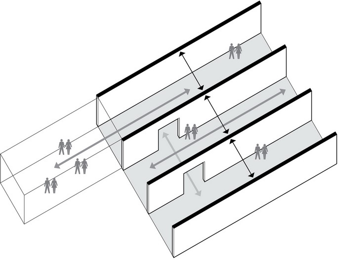
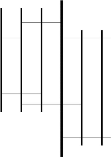
- A pair of bearing walls defines a field of space distinguished by a strong directional quality toward its open ends. This fundamental type of structural pattern is often used in projects consisting of repetitive units, such as multifamily housing, because they simultaneously serve to isolate the units from one another, curb the passage of sound, and check the spread of fire.
- A series of parallel bearing walls can organize a series of linear spaces, with the solidity of the bearing walls being able to accommodate varying degrees of slippage or offsets, from small to large.
TRANSITIONAL PATTERNS
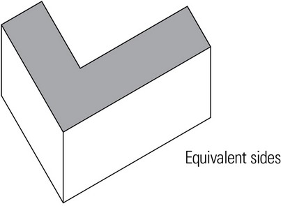
Corners define the meeting of two planes. Vertical corners are architecturally significant because they define the edges of building facades in elevation and simultaneously terminate two horizontal directions in plan. Related to the architectural nature of corner conditions are constructibility and structural issues. A decision based on one of these factors inevitably influences the other two. For example, the adjoining sides of a one-way spanning system are inherently different, which would impact the architectural relationship and design expression of adjacent facades.
- If two planes simply touch and the corner remains unadorned, the presence of the corner will depend on the visual treatment of the adjoining surfaces. Unadorned corners emphasize the volume of a form.
- A form or one of its faces can dominate an adjacent mass by continuing to and occupying the corner position, thereby establishing a front for the architectural composition.

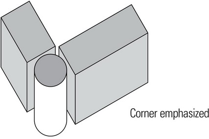
- A corner condition can be visually reinforced by introducing a separate and distinct element that is independent of the surfaces it joins. This element emphasizes the corner as a vertical, linear element that defines the edges of the adjoining planes.
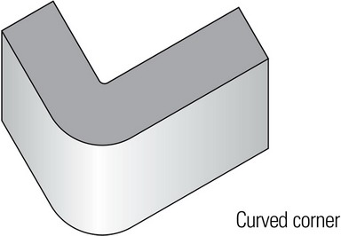
- Rounding off the corner emphasizes the continuity of the bounding surfaces of a form, the compactness of its volume, and softness of its contour. The scale of the radius of curvature is important. If too small, it becomes visually insignificant; if too large, it affects the interior space it encloses and the exterior form it describes.
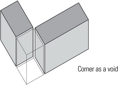
- A void diminishes the primary corner condition, effectively creates two lesser corners, and clarifies the distinction between two separate forms or masses.
The plan diagrams that follow present alternative approaches to structuring these types of corner conditions, each of which has architectural implications.
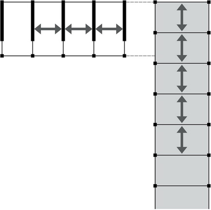
Equivalent sides
- One-way framing or spans of the side bays lead to the two-way framing or span of a square corner bay, establishing an equivalency of the adjacent sides.
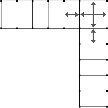
- This situation is similar to the one above, but in this case, the two-way framing or spans of square bays continues along both wings. Note that the continuity that contributes to the efficiency of two-way systems only exists in one direction in each wing.
- The one-way framing or spans of one wing of the building continues to the corner position. For the adjoining facades to be equivalent, a column would have to be added to the longer side of the end bay.
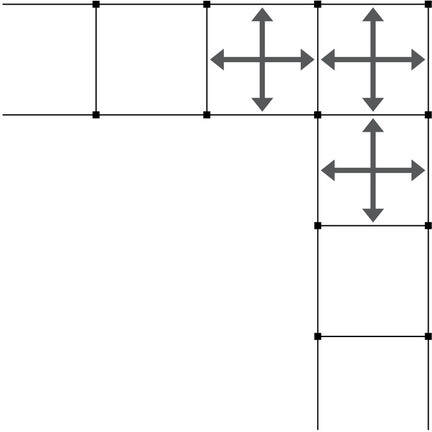
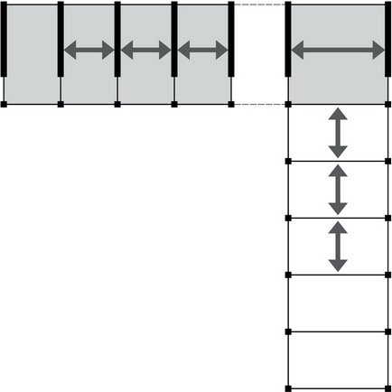
One side dominant
- One-way framing or spans in one wing leads to the two-way span of a square corner bay, diminishing the stature of the other wing. A void between the two wings emphasizes the separation between the two wings.
- This situation is similar to the one above, but here the one-way framing or spans in one wing continues unchanged to the corner position, giving the arrangement a definite sidedness.
- The one-way framing or spans of one wing, while picking up the spacing of the other wing in one direction, dominates due to its material and type of structure. The corner bay requires a longer one-way spanning system.
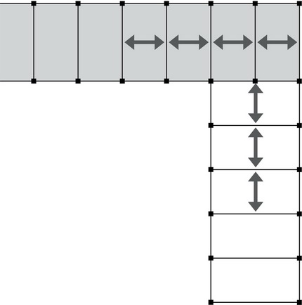
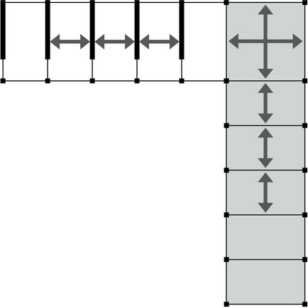
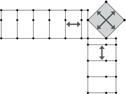
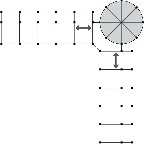
The three plan diagrams that follow illustrate how a corner condition can be made special or unique through the significant size, distinctive shape, or contrasting orientation of a discrete corner element.
- The square corner bay is enlarged to emphasize its primacy over each wing, which maintains its own one-way framing or spans. Two columns are added to ease the transition from the smaller bay spacing of the wings to the larger corner-bay spans.

- The square corner bay is rotated to emphasize its corner position while each wing maintains it own one-way framing or spans. Two columns are added to support the corners of the rotated bay.
- The circular corner bay contrasts with the rectilinear geometry of each wing, emphasizes its corner position, and requires its own structural pattern. Each side can be framed as a one-way system with beams linking each wing to the corner bay.
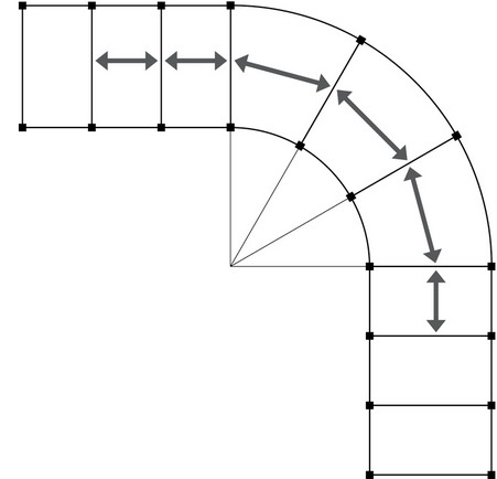
Corner as Void
- The repetitive spans are reduced in the wedge-shaped corner bays. The convergence of the radiating framing members at a single interior corner column is a difficult connection to make.

- Increasing the radius of curvature of the wedge-shaped corner bays allows longer spans and avoids the awkward intersection of six spanning members as shown above.
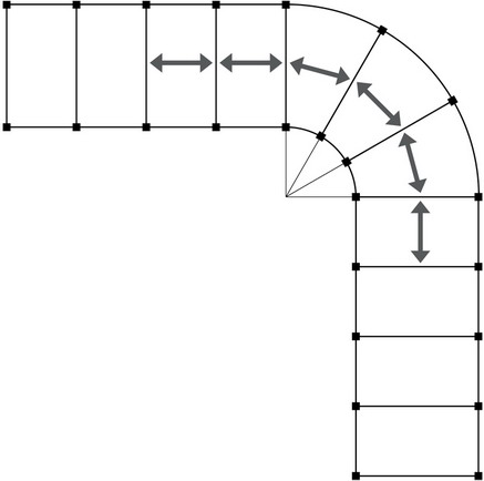
- Increasing the radius of curvature even more results in longer, more variable spans.
- Both wings can be structured independently of each other but be tied by a transitional corner bay.
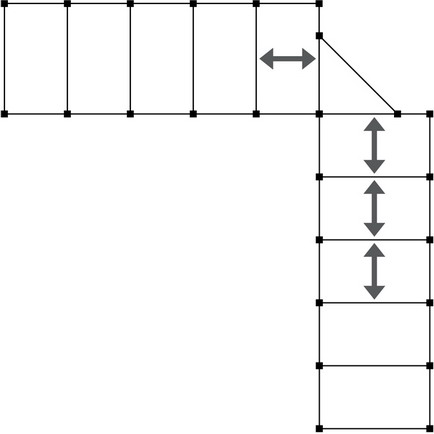
- The corner void emphasizes the independence of each wing, which are joined at a single column.
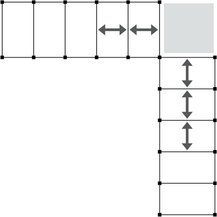
- Both wings are independent structural systems related only by proximity.
PATTERNS IN CONTEXT
Foundation Grids
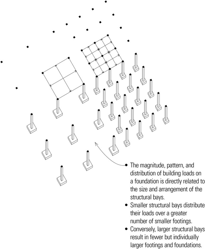
The primary function of a foundation system is to support and anchor the superstructure above and transmit its loads safely into the earth. Because the foundation serves as a critical link in the distribution and resolution of building loads, its pattern of supports must be designed to both accommodate the form and layout of the superstructure above and respond to the varying conditions of soil, rock, and water below.
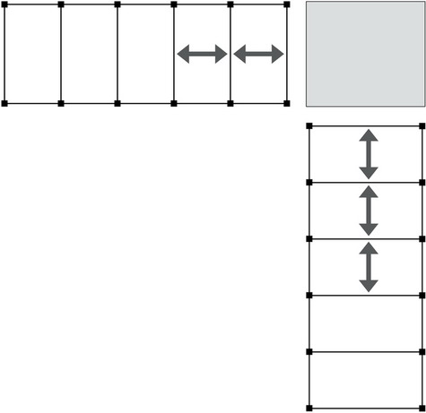
The bearing capacity of the supporting soil will impact the choice of a foundation type for a building. Shallow or spread foundations are employed when stable soil of adequate bearing capacity occurs relatively near to the ground surface. Footings are proportioned to distribute their load over a wide enough area that the allowable bearing capacity of the soil is not exceeded. This should ensure that whatever settlement does occur is minimal or is uniformly distributed under all portions of the structure.
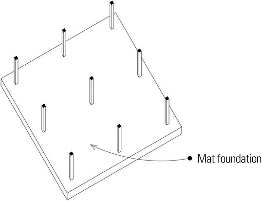
When the bearing capacity of the soil on a site varies, spread foundations may be joined by a structural plinth or mat foundation—essentially, a thick, heavily reinforced concrete slab. Mat foundations distribute concentrated loads to areas of higher-capacity soil to avoid the differential settlement that would occur between individual spread footings.
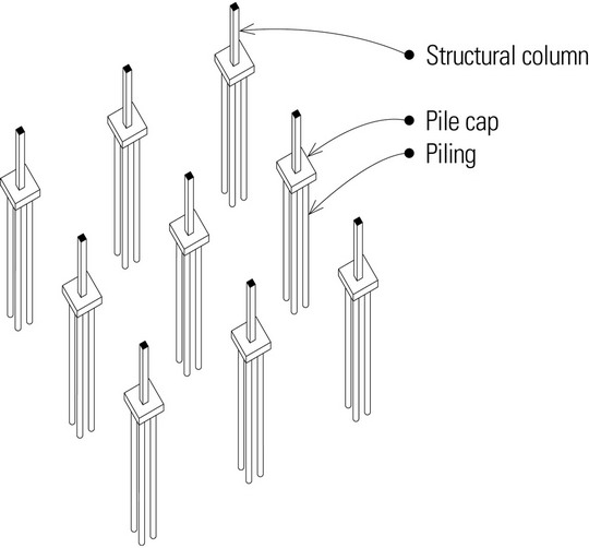
When building loads exceed the bearing capacity of the supporting soil, pile or caisson foundations must be used. Pile foundations consist of steel, concrete, or timber piles that are driven into the ground until they reach a more suitable bearing stratum of dense soil or rock or until the friction of the soil on the piles is sufficient to support the design loads. Individual piles are typically joined with a cast-in-place concrete cap that in turn supports a building column.
Caissons are cast-in-place concrete shafts that are created by drilling the soil to the required depth, placing reinforcing steel, and casting the concrete. Caissons are generally larger in diameter than piling and are particularly suited to slopes where lateral displacement is a major concern.
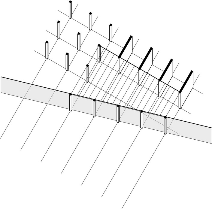
Building on Slopes
Pile foundations can be used on irregular or sloping topography, particularly where the surface soil on the slope may be unstable and the pilings can extend down to bear on or in more stable stratum of soil or rock. In such cases, it may not be necessary to retain soil, and the location of the piles can align with the desired column locations in the building.
When it is desirable or necessary to excavate into a slope, retaining walls are often employed to contain the mass of earth above the grade change. The retained soil is considered to act as a fluid that exerts lateral pressure on the face of the retaining wall, tending to cause the wall to slide laterally or to overturn. The overturning moment created by the lateral soil pressure and the opposing resistance of the wall’s foundation is critically dependent on the height of the wall. The moment increases with the square of the height of the earth that is retained. As a retaining wall becomes taller, it may be necessary to install tiebacks to piling or to build in counterforts—cross walls that stiffen the wall slab and add weight to its footing.
A series of retaining walls parallel to the slope can provide continuous support for bearing walls in the superstructure of the building. It is not advisable to add the weight of the building to the soil behind the retaining wall. The location of the retaining walls should therefore coincide with lines of support in the building above.

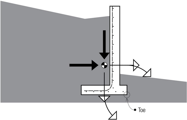
A retaining wall may fail by overturning, horizontal sliding, or excessive settling.
- Thrust tends to overturn a retaining wall about the toe of the base. To prevent a retaining wall from overturning, the resisting moment of the composite weight of the wall and any soil bearing on the heel of the base must counter the overturning moment created by the soil pressure.
- To prevent a retaining wall from sliding, the composite weight of the wall times the coefficient of friction for the soil supporting the wall must counter the lateral thrust on the wall. The passive pressure of the soil abutting the lower level of the wall aids in resisting the lateral thrust.
- To prevent a retaining wall from settling, the vertical force must not exceed the bearing capacity of the soil.
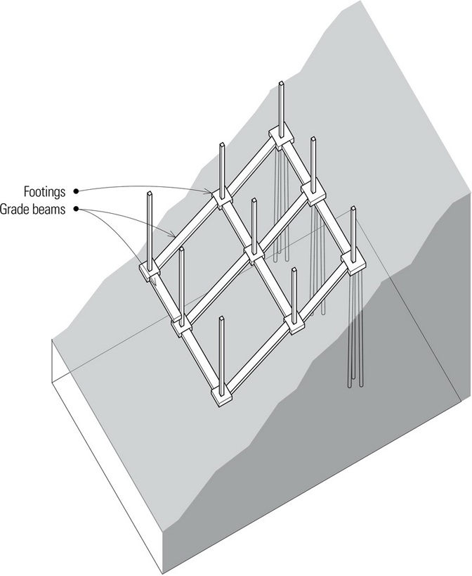
For small projects, particularly when the design does not require excavation into a sloping site, grade beams may be used to tie the foundation into a single, rigid unit that is in turn anchored to piling, usually at the upper portion of the site. This has been successful where minimum disruption of the site is desirable and on sites that are primarily accessible from the high side.
When the design does not require excavation into a sloping site, the foundation walls may run perpendicular to the slope and be stepped to follow the topography. Because stepped foundation walls do not retain earth, they will typically not require the reinforcement and large footings of a retaining wall.

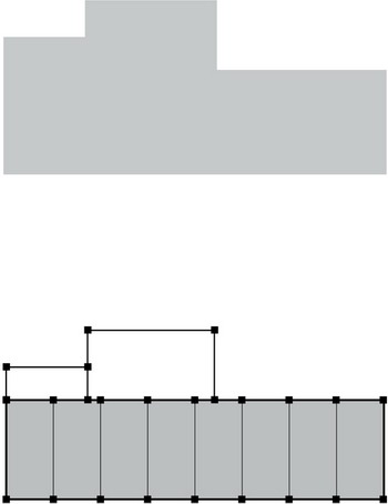
Parking Structures
When parking is the sole purpose of a structure, the specific dimensions required for maneuvering and parking vehicles dictate the possible column locations for the layout of the structural bays.
When parking is an ancillary function in a building, it is typically located on the lower floors of the structure while other uses occupy the upper floors. It is often difficult to resolve the structural grid that is appropriate for the upper floors with one that effectively accommodates parking. Overlaying the two conditions may identify a possible common grid between the two by taking advantage of the flexibility of column locations suggested in the diagrams on the following page.
Where column alignment is not possible, it may be feasible to use transfer beams or angled struts to carry the loads from the upper floors through the parking floors to the ground foundation. It is always desirable to minimize these conditions.
Mixed-use buildings in which two uses, such as parking and housing, require a specific degree of fire separation, may have the roof of the lower parking structure constructed as a thick, posttensioned concrete plate. The plate is able to transfer column or bearing-wall loads from the upper floors to the parking structure while providing the required fire separation. This is only feasible when the upper structure is subject to relatively light loads and is likely not cost-effective if there are large concentrated loads or when the misalignment between columns creates concentrated loads in the middle third of longer spans.
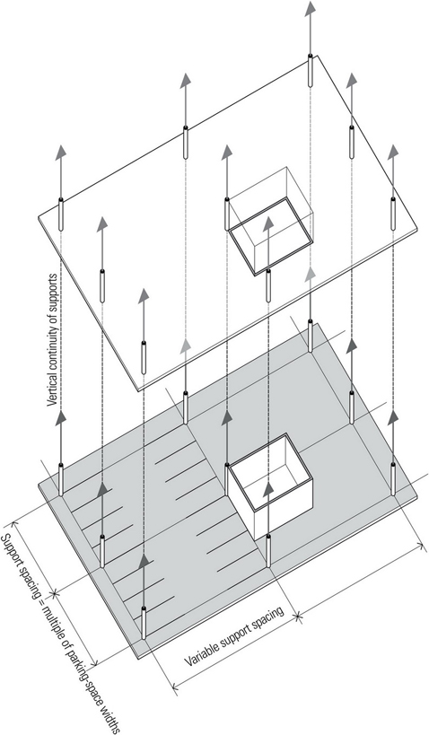
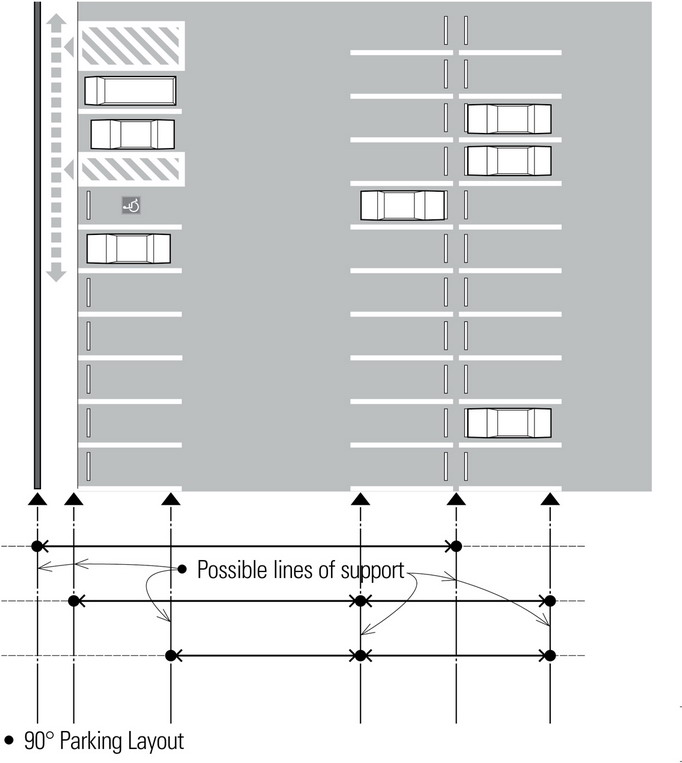
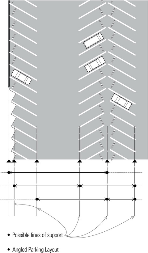
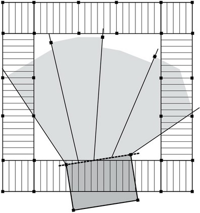
The columns in a parking structure should, if possible, be placed between adjacent rows of parking spaces in one direction and at some multiple of the width of the parking spaces in the other. The layout should allow sufficient space for cars to maneuver and car doors to open unimpeded. Columns should be visible to drivers when backing up. This will often result in moderately long spans in the range of 60 feet (18 m).
However, as the plan diagrams show, there are alternative locations for column supports. The black triangles indicate possible lines of support along which columns can be spaced in concert with the width of the parking spaces. One can see that a variety of span lengths are feasible, making it possible for a particular layout to be coordinated with the column support pattern in the structure above.