 GLOBAL POSITIONING SYSTEM (GPS)
19 SATELLITES AND RADAR
It’s worth beginning this chapter by setting satellite navigation into historical context – if you can call it history, it’s so recent! The first edition of this book was written in 1993, when the American Global Positioning System (GPS) had been theoretically available to worldwide civilian users for just 12 months. I was probably typical in that I bought my first steam-powered handheld set in 1994, but the revolution was only really completed in the first decade of the 21st century. As late as the 2nd edition (1997), the awful ‘doppler satnav’ was mentioned, and it was not until the 3rd edition in 2000 that Radio Direction Finding (RDF), a WWII standby that now seems primitive beyond belief, received the final ‘chop’ from these pages. Even then, column space was set aside for Decca and Loran C, hyperbolic radio fixing systems now superseded in yachts, although Loran C is currently under review as a terrestrial-based backup system. Electronic fixing became the official basis of navigation with the establishment of GPS and finally came of age with the associated chart plotters. The politically independent European parallel system, Galileo, waits just around the corner.
For this book, the term ‘GPS’ will be used to include any Galileo-based systems that may supersede it for European users within the lifetime of this edition. Should this come to pass, it is unlikely to alter anything in principle for the on-board navigator. Whether or not any changeover will cost the beleaguered yachtsman yet more money remains to be seen.
Even the most basic marine GPS receivers now offer at least a lat/long fix, full waypoint facilities and route planning. So many different instruments are available that it would be unrealistic to give instructions here regarding which buttons to push. The only sensible way ahead is for a skipper to self-educate concerning the specific equipment selected. In the old scholar’s phrase, ‘Read, mark, learn and inwardly digest’ the manufacturer’s instructions, and don’t rely on the gear until you fully understand what it can and cannot do. Below are some notes that may prove helpful, but they are by no means all you need to know. The same holds good for radar, where any user will be well served by a short course or at least one of the specialist books on the subject.
A sound electronic system, properly installed aboard a well-found vessel, is now the core of many a good navigator’s art – and used well, it can make a good navigator even better. If any of these criteria is missing, over-reliance on electronics can lead to serious trouble. Their arrival and acceptance on the scene has transformed the accuracy of offshore navigation and removed much of the stress from a skipper’s life, but they have done nothing to change the navigator’s basic philosophy that input from one source alone is always to be treated with caution.
The dangers of standing into a tight corner on a lee shore while relying utterly on a navigation system dependent on voltage – even with a back-up hand-held set powered by its own dedicated batteries – speak for themselves. Also, GPS aerials are best sited at or near deck level and so are vulnerable to physical damage. Many an antenna has been kicked off its perch by enthusiastic crew activity. It is also stretching things to place your life at the mercy of a group of satellites, up there primarily for military purposes, which we are permitted to use with the proviso that they may be switched off without warning. For all these reasons, the first page to flash up on a chart plotter is usually some sort of disclaimer telling you that if you really must use this product for navigation, you do so at your own risk. The same could, of course, be said for the magnetic compass, so we must all make our own peace with ourselves and not be too perturbed by manufacturers whose fear of litigation seems their paramount nightmare.
GLOBAL POSITIONING SYSTEM (GPS)
GPS supplies accurate three-dimensional fixes 24 hours a day, in all weathers, anywhere in the world, even though for maritime purposes, two dimensions will do very nicely. The system in general use in 2014 is operated by the US military establishment, with Galileo waiting in the wings. Galileo’s likely parameters of operation are not known at the time of writing, but in order to preserve US national security, those in charge of GPS are ‘dedicated to the development and deployment of regional denial capabilities in lieu of global degradation’. In plain speaking, this means that rather than downgrade the signals globally or turn off the satellites completely, sensitive areas can be blacked out from GPS signals.
To deliver the GPS system, a constellation of 21 satellites has been arranged in a ‘birdcage’ around the Earth, together with 3 stand-by ‘spares’. Their extremely high altitude keeps them clear of skywaves and other atmospheric interference. It also guarantees that four or more can be seen from a given location at any time. The system is completed by various control and monitor stations around the world. These maintain system accuracy, together with other forms of monitoring and updating of the navigation message of each satellite.
GPS works by knowing the satellites’ position in space. Each of them transmits coded data which includes a radio signal timed to mind-numbing accuracy. This enables the receiver to calculate the distance of the transmitting satellite from its antenna, which gives it a position line on the surface of a sphere centred at the satellite. The receiver chooses the three or more satellites offering the best ‘cut’ of position lines (position spheres in reality) and works out its position from these (Fig 19.1).
Control of GPS accuracy
GPS is capable of producing fixes accurate to better than 1 m, but this Precise Positioning Service (PPS) is kept by the military for themselves by encrypting the signals. The rest of us must be content with a theoretical potential accuracy of around 5 m. In practice, fixes are rarely adrift by more than a boat’s length or two. Such discrepancies should be of no more interest to the marine navigator than his altitude, but with so high a degree of potential accuracy it’s easy to get carried away, so we end-users must remember that a fix is only as good as the chart it’s plotted on. The surveyor’s brief may not have allowed for such knife-edge potential, and if the unit is working with a paper chart or the electronic cartographer has committed a faux pas, failure to set up the receiver for the correct datum (see below) renders all such niceties a nonsense.

 Fig 19.1 GPS fixes are deduced from the intersection of ‘sphere of position’.
CHART DATUMS
The globe is not a perfect spheroid. Its surface has minor irregularities. In the days before the phenomenal accuracy of GPS, the various charting authorities were content to work within a generally agreed mean latitude and longitude grid. If one nation’s convention varied from another’s by a few metres, as it did and sometimes still does, no practical navigator was interested. The difference was largely unobservable by conventional means. Because of the precision of GPS, all this has changed.
| SKIPPER’S TIPS | Differential GPS |
| This feature is not relevant to most yacht navigation at the time of writing (2014), but it should be understood lest the current situation change. | |
Differential GPS (DGPS) upgrades the accuracy of the standard GPS position by comparing the GPS-fixed position of a static, ground-based receiver at any moment with its known geographic position. The ground station transmits signals to all GPS receivers in its vicinity, advising them of any error it has noted. The differential user’s receiver then incorporates this data into its fix. Accuracy of a metre or so can be expected. |
|
When any on-board GPS is reading out its fixes to the wrong ‘datum’ for the chart in use, the plot could be in error by, at the extreme, up to several hundred metres. Datum shifts of a cable or so (0.1 nm) are common place. Fortunately, the majority of receivers will now read out in any one of a variety of datums.
Check the ‘title corner’ of your chart. If it is reasonably modern you will find a statement of datum, e.g. ‘WGS84’ or ‘OSGB (1936)’. The GPS default setting is WGS84, favoured by the US and rapidly becoming the world standard. Some charts do not declare their datum, but give an instruction concerning how to shift ‘satellite-derived positions’ instead. If this is so, set your GPS to WGS84 and do what the chart says if ultimate accuracy is required. If it isn’t, as is often the case, don’t waste your time with the extra plotting duties.
Most electronic charts have been fine-tuned so that fixes displayed on their associated chart plotters are accurate. Whether this is done by redrawing the chart to WGS84 or by some other computer wizardry is not important to the practical user. Suffice to say that it generally works. However, I have personally seen more than one case where a chart somehow slipped through the net, with a potentially dangerous outcome. The message is obvious. Vigilance, and the old standby of input from more than one source.
Modern charts are increasingly being printed to WGS84, but until every chart aboard every boat is set to this, the issue of datums will remain a serious one. Failure to address it can lead to serious errors in a world where so much accuracy is now assumed.
BEYOND THE FIX
Some traditional navigators use GPS for nothing more than fixing their position on a paper chart. This is their choice, but it must be said that in doing so they are not reaping the full value from their investment. The additional functions offered by all GPS receivers have really given rise to what is in effect a modified and much simpler system of passage navigation.
Course and speed
These can be read out from most yacht navigation systems. The machine is, of course, working this up by comparing fixes. These relate to your actual position, so the course and speed are ‘over the ground’, rather than ‘through the water’ and the acronyms COG and SOG have entered the vernacular. Do not fall into the trap of imagining that because the GPS reads 9.3 knots, your 28-footer is logging anywhere near this velocity. Check the water log and the tidal stream atlas and re-enter the real world.
One use to which this information can be put is to check your set and drift against that predicted by the tide tables (see Chapter 15). Always remember, though, that any information lifted from the set in this way is, like a fix, passé a second after you have written it down.
Waypoints
The idea of the waypoint forms the heart of modern navigation. You may choose to use few or many, but the concept must be understood and accepted so that you can make an informed decision based on the way you think and the circumstances.
It is standard practice to enter a number of predetermined positions along a predicted route into your navigator’s computer. The theoretical ideal for a passage of any substance, offshore or along the coast, is to proceed from one of these waypoints to the next. This can be done informally, plotting them as you go, or as a pre-planned ‘route’. More information about way points and how they should be selected and used will be found in ‘Passage Planning’ (Chapter 22). Waypoints are helpful on a chart plotter, if for no other reason than that an active waypoint reads out its distance, ‘time to go’ (TTG), ETA etc. With a paper chart they ease your task in many ways.
GoTo
By activating the ‘GoTo’ function, the receiver will lock on to a waypoint, giving a constantly updated distance and bearing to it. Distance and bearing to a known position is, of course, another form of expressing the yacht’s position (Fig 19.2). This can often be a more convenient way of plotting a fix on the chart than trying to wrestle with lat/long over the folds of the paper with a chart protractor or parallel rule that is too short and a longitude scale that numbers from right to left in west longitude. As an aside, the concept of defining a fix in terms of lat/long and range and bearing is useful when transferring a position from one chart to the next. It is all too easy to make an error over a question of scale, or by reading the longitude the wrong way. If you transfer the position by both means, they should marry up; if they don’t, you’ve made a mistake.

Fig 19.2 A position can be expressed either as lat/long or as a range and bearing from a known, charted object.
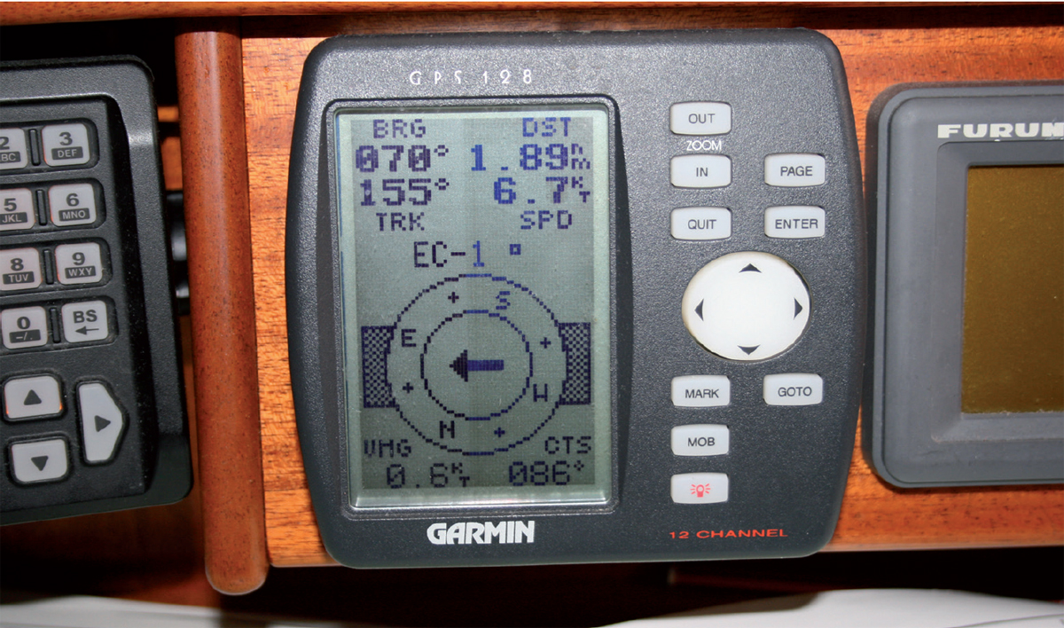
A simple GPS GoTo waypoint readout.
Using GoTo for comparing the bearing of the waypoint and the present track makes adjusting your course to take you to it a doddle, always given that the tidal stream or current is expected to remain reasonably steady. Just steer to keep your COG the same as the bearing and you’ve cracked it.
Ghost waypoints
Where a leg of your passage looks like passing across a large section of chart without the need for a natural waypoint, it is worth creating a ‘ghost waypoint’ purely for plotting purposes. If you make this the middle of a compass rose, plotting to or from it will be a breeze. More and more charts are doing this for you by means of so-called ‘Plotter Reference Points’. Enter the relevant ones as waypoints and they will be most useful.
Danger waypoints
Where an isolated, unmarked danger lies athwart your direct route and you don’t mind which side you pass it, there’s much to be said for placing a waypoint actually on top of it. Then, as it approaches, all you have to do is activate it and make sure its bearing keeps changing. You can’t possibly hit it then! The hardware plotter on my boat has a choice of waypoint symbols. One of them is a skull and crossbones. Ideal for danger waypoints, although normally I prefer the smiling face option.
Plotting waypoints
Waypoints are conventionally plotted on a paper chart as a small square around the pinpoint of the actual position. They are labelled with a name, a number or a letter:

Cross-track error
Your GPS receiver is aware of the direct track from one waypoint to the next, or from a defined position to a pre-entered destination. It will always be delighted to advise you as to whether or not you are off-track, which side you are off, and by how far, which is sometimes valuable to know.
Many receivers will also offer you a course to steer in order to return to the line, but this must be treated with intelligent caution. If staying on track is crucial to your safety, you should determine whether the recommended heading could lead into trouble from your present off-track position. There may, after all, be dangers in the way, and the GPS will not know about them.
Even if the path is clear, the computer is often so desperate to get you back on to the original track that it demands an alteration so radical as to be irrelevant, particularly in a sailing boat. More often, it is better just to steer ‘up’ or ‘down’ by 20° or so until track is re-established. The cross-track information is sometimes sufficiently unimportant for you to ignore the old track and opt instead for a fresh departure to the waypoint from where you are now. Pressing GoTo will generally restart the process. Maybe you can even miss out that waypoint and proceed towards the following one. The processor won’t consider any of these options, so don’t let it patronise you.
Despite these cautions, cross-track error can be extremely helpful down the last mile or two on to a landfall in thick weather. Under certain circumstances it can also guide you through a series of dangers close by on either hand, but before you consider using it for this, refer to the caveats in Chapter 23.
Except for the fastest power craft, cross-track error should not be considered a substitute for pre-planned course shaping over extended periods, particularly where a turn of tide is involved. Employing it for this purpose will see you steering into the stream regardless of the overall strategic situation. You may well therefore sail considerably further through the water than is necessary. If this sounds like theoretical hot air, take a look at Chapter 20 for the reason.
Man overboard function
This is standard equipment in most GPS receivers. If you suffer a crew member over the side and hit the ‘MOB’ button immediately, the inbuilt course computer will give a range and bearing back to the geographic location where the casualty was lost. It does this by creating a waypoint marked as ‘MOB’, then activating the GoTo software to keep you informed of what you need to know most of all – where the casualty lies in relation to you. This can be a lifesaver on a dark night, but you must be aware of its limitations. The position given is a position on the seabed. The boat and the casualty are both subject to any current or stream that is running. Their position in relation to one another is governed by the yacht’s movements alone, and both are drifting downstream at a constant relative rate. The geographical position given by the computer remains where it was, but any current will be carrying both the yacht and the subject away from it. A mere 2 knots of stream will shift the victim a cable (200 yards) downstream of the waypoint in 3 minutes. Nevertheless, it is generally well worth the 10 seconds it may take to hit that button, so long as you note the time. If you should lose touch with your casualty and are within range of Search and Rescue services (SAR), they will be able to calculate the lost person’s set and drift with surprising accuracy, working from the time and the fixed MOB position. Activating the function without glancing at your watch will degrade this accuracy severely in areas of strong current, unless your computer will read out the time as well as the fix, which many do not.
ELECTRONIC CHART PLOTTERS
The electronic chart plotter started life as a computer screen depicting a caricature of a paper chart. Now they deliver full-quality coloured chart cover age with a zoom facility to take the user from global scales down to the local marina pontoons. Some even offer overlaid satellite photographs and 3D charts, although the value for money these represent to serious navigators seems up for argument.
The plotter’s computer either interfaces with GPS or contains its own GPS facility, so that the yacht’s real-time position is shown on a chart on its screen.
Types of chart plotter
The hardware plotter
This is a single, dedicated instrument incorporating a screen, a processor and a GPS receiver. It will perform all the functions of a simple GPS set with the additional benefit of showing the boat on the chart in a moving, real-time position. Hardware plotters generally use a specific type of chart pack age so you need to decide which one gives the best deal for the charts you are going to want. It’s also important to decide which charts appeal to your eye, because they are all vector charts and they all look a little different.
Hardware plotters often come as part of a larger package of instruments. As such, they can be interfaced in all sorts of directions, such as showing AIS contacts on the electronic chart in real time. Another common interface is with radar, and some can display the radar image as an alter native on the screen. Split screens may be available so you can access both tools at once. Some even overlay the radar image on to the chart, which is of enormous value to the trainee radar operator – a state beyond which few honest yacht sailors progress.
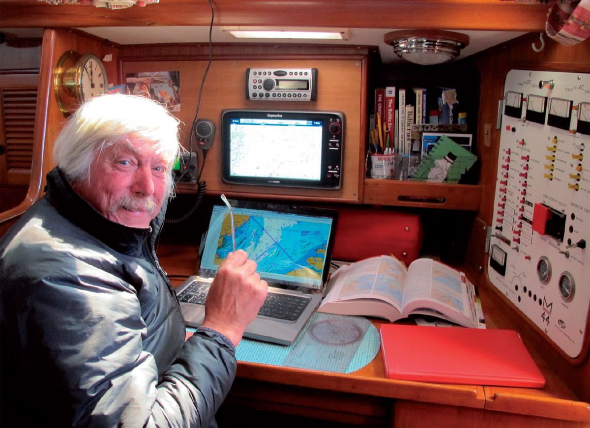
The author’s chart table today. A Raymarine E-series bulkhead chart plotter interfaces with radar, AIS etc. The PC is running ARCS charts on a Meridian Chartware plotter program with its own independent GPS and battery. Note also the paper log book in the foreground and the nautical almanac, the twin bibles of the serious navigator.
The software plotter
A software plotter is a plotter program installed, together with a chart package, on to a boat’s PC. Many people use laptops for this, but an inbuilt PC can be even better in certain applications. The PC is interfaced with an independent GPS receiver via the NMEA data protocol through a serial or USB port connection. The combination is capable of doing most things a hard ware plotter can do, and often much more besides. It has the advantage that since most people now have a laptop, the ‘hardware’ is already in place, so all that need be bought is the software. Another benefit software plotters offer for some of us is that they can use raster charts (see Chapter 12) which many consider to be clearer and more user-friendly. The time was when con figuring and interfacing a PC-based system was more of a challenge than a hardware plotter, which in its simplest form you buy, set up the antenna and plug in. As electronics proliferate, this is often no longer the case. Many plotters today are interfaced with all manner of other devices, from autopilots to AIS receivers. The manuals for installing this sort of kit are beyond the capacity of many a university-educated mariner. Whether this is their fault or his is up for debate, but the bottom line is that this stuff is not getting any easier for Jolly Jack the sailorman. Fitting up a PC might seem simple by comparison.
Apps, tablet and phone plotters
The second decade of the 21st century has seen the arrival of inexpensive plotter software and electronic charts to use on tablets including the iPad and on smart phones. Most of us now have such a phone in our pockets and to be able to whip it out, hit an App and see the whole picture on a unit entirely unconnected to the ship’s systems, using an independent battery and GPS, is a phenomenal addition to safety. The chart is, of course, too small for a primary navigation system, but as backup or a quick reference that costs under £20, the value is remarkable. Phone Apps generally include full tidal height data and graphs, as well as measuring tools and projected track vectors. Tablet plotters are similar to phone units but have more features and clearer charts. The Apps cost somewhat more, but are still less than you’d pay for a decent meal out. Add a waterproof case and you have a cockpit plotter with a screen-size that is perfectly usable. Features are in short supply when compared with a full bulkhead plotter and interfacing is not really available today. Nonetheless, especially for pilotage, a tablet can transform the navigator’s life.
When selecting a phone or tablet plotter, make sure it has a projected track feature (see below, and not to be confused with a ‘heading’ vector). Some do not, and a plotter without projected track is like beer without skittles. One that I have been using is stuffed with software I never use yet fails to address this vital issue. To be able to see instantly where a heading will take you is the best thing that has happened in navigation since Harrison’s chronometer. Why a plotter manufacturer would leave it out is beyond me, but I would counsel vigorously to avoid any such product.
General functions of chart plotters
Zooming, panning and overviews
The biggest problem with chart plotters is scale. If you can see enough of the chart to achieve an overview, you don’t have sufficient detail to see what you’re about to hit. This is dealt with by zooming in and out, and panning across the chart. Learning how to do this is not only a physical process, it also requires a jump of consciousness for anyone brought up on paper charts. Larger plotters can actually be used without paper charts by a skilled operator (always given paper backup), but small-screen units really need a paper chart standing by continually to fill in the big picture. Nonetheless, the real-time fix on a medium-sized portable plotter is a fantastic help to eyeballing your way through a navigation problem.
Vectors and projected track
The projected track vector is the most important single navigational break through since the chronometer. By activating a line projecting from the boat, a plotter can show where she will be after a given time, always assuming that her course over the ground remains constant. In the safe hands of a navigator who understands the variables, this is the most remarkable aid to security because it has, to all intents and purposes, already calculated set and drift, and applied them to your heading. Find out how to activate it, then switch it on!
Ship’s heading
In addition to projected track, a good plotter can also indicate your ship’s heading with a second vector, perhaps of a different colour. This may well demand calibration and perhaps interlinking to an autopilot, which can lead to difficulties in other than expert hands. Once it’s working, however, it allows you to see at a glance the extent to which your track and heading are at variance.
A third vector sometimes available is the current, deduced by the processor from the difference between your COG/SOG and your heading/boat speed. In a third colour, this one only works if your heading vector is ‘trimmed’ correctly. It has its uses, but obsession with such things can lead to failure to look out of the window where real life continues to deliver ‘slings and arrows’ that are not virtual and which really hurt.
| SKIPPER’S TIPS | Naming the features |
| Be careful with American-built plotters, which may use different names from European units. Often designed with fast motorboats and low tidal stream values in mind, they may use a faint colour for the all-important COG and a bold one for the far less important ship’s heading. They may call ground track (COG) ‘course’, with no mention of ‘over ground’ anywhere to differentiate it from ‘course steered’. Make absolutely sure your plotter is speaking your language or, if it isn’t, that you know what it is talking about. | |
Bearing and distance to cursor
To relate your position to a charted object, you have only to hover the cursor over it and range and bearing are displayed. This gives you an alternative means of recording your position which is more convenient and often more relevant than a straightforward lat/long. I tend to use this as I approach landfall, keeping to lat/long out of sight of land.
| SKIPPER’S TIPS | Range and bearing from the ship |
| Click into this feature if the plotter has one, then click the cursor on to an object on the electronic chart. The changing range and bearing of the object will be displayed until you switch it off. | |
Dividers
Most good plotters offer electronic dividers to measure the bearing and distance between any two points. Very useful for passage planning. On some PC plotters it is possible to use multiple sets of dividers and leave the lines ‘active’ on the screen. This enables you to plot visual fixes or vector diagrams for tidal navigation, etc. Sadly, few hardware plotters offer this multiple facility. If their GPS goes down, they are therefore useless. A plotter allowing multiple lines to be constructed can be used just like a paper chart, even without GPS. I have even plotted running fixes (here) on a PC.
Tidal heights
Many vector chart/hardware plotter programs now allow you to access comprehensive tidal height information at the click of the cursor. PC-based plotters may require additional software for this, but the effect is the same. No more secondary port interpolation nightmares! (See Chapter 14.)

Most modern plotters using vector charts carry some sort of tidal height calculator. This one is from a Navionics App. Click on the diamond ‘T’ for all you need to know.

A full tidal height graph that defaults to today but carries data for the foreseeable future is revealed by clicking on the tidal height diamonds found all over some vector charts.
Tidal streams
As recently as 2007, hardware plotters were not yet offering this data directly, although some could deliver a very crude ‘maximum current’ figure related to High and Low Water. The more powerful plotters could read out the present deduced set and drift. In 2014, tidal streams of a sort can now be found deep in the menus. Many software plotter programs can overlay tidal vectors on to the chart and some even work out courses to steer to compensate. Don’t accept their word as gospel, however, until they have proved their worth. I have a good setup on my own boat, but the results are not as reliable or accurate as those I compute for myself using a tidal stream atlas.
Autopilot interface
A fully interfaced yacht has her plotter hooked up to the autopilot. This enables the display to show heading as well as ground track (COG). Such systems can be programmed to have the processor effectively take command. It sets the courses to steer the boat to the next waypoint, then alters to another down the route, and so on until, at some stage, it must be deactivated to pilot into the berth. Sailors may find this a frightening prospect, but many motorboat skippers use it all the time. It goes without saying that such a feature must be treated with more than nominal respect for the potential hazards it can bring to the unwary.
Waypoints on a plotter
Inputting waypoints to plotters is extremely simple, sometimes requiring no more than positioning a cursor on the spot and clicking the mouse or ‘enter’ button. This makes setting up a route far, far easier than on a numeric GPS unit, where you’d think the number punching was going on until the last trumpet. Plotter waypoints can be linked as routes by dragging the cursor from one point on the planned passage to the next, clicking them in as you go. If you leave a line joining the waypoints, you can see at a glance whether the chosen route is safely clear of dangers.
I find this somewhat ironic, because it could be argued that waypoints are less universally applicable to plotter navigation than they are to GPS/paper chart. The plotter shows you the boat. It also projects where she is actually going, so if you want to arrive at a buoy and you can see you’re 5° off track, effective adjustment couldn’t be easier. You don’t necessarily need a waypoint on the buoy as you would have done without the graphic display. If you can’t find the projected track function, just pop the cursor over the buoy, note how its bearing compares with your COG and adjust the course accordingly.
Information on the active waypoint is naturally comprehensive on a plotter, often with special ‘screens’ to display it, so if you enjoy waypoints or if circumstances demand one, you are, as you might say, in the guinea seats anyway. Among certain others I find useful, I always input a waypoint at my destination, if for no other reason than that it shows instantly how far I have to go and an ETA.
The list of features of the modern plotter is long and growing every year, so the best advice I can give is that we keep our eyes on the ball. Chartwork is not really that complicated and, with the best will in the world, manufacturers and programmers do have a tendency to install features just to show that they can. Explore your plotter thoroughly, decide which bits you want, then become its master. It will serve you well.
MARINE COMPUTERS
There seems little doubt that the long-term future of all but the most frugal small craft navigation lies with chart plotters. For some who grew up before GPS or even Decca, this may be a hard pill to swallow, but the fact that the mind-rattling technology became commonplace within five years of its realistic arrival on the scene tells us how much most of us really want it.
At the time of writing, many ‘medium-tech’ yachtsmen are using general-purpose laptop computers to run chart programs, but for larger yachts, dedicated ship’s computers are already becoming the norm. Among such basics as running major chart plotters, these compact, powerful tools can superimpose weather maps downloaded via low-cost email ‘Grib’ files on to passage charts. The met data can be processed by the computer to give the best course to steer for speed or comfort, while ‘what if’ scenarios allow at least a modicum of intuition to be applied to this powerful flow of information. Notices to mariners, conventional weather data, the opening times of your favourite restaurant: the flow of information is growing annually. Whether you want it is up to you, but it’s getting easier to obtain all the time. Emails and internet go without saying, of course, but you can even watch your favourite DVDs if you finish your handy pocket copy of the Complete Works of Shakespeare.
It’s a far cry from me setting out across the English Channel in 1971 with an old chart, a pair of schoolboy dividers and a set of parallel rulers I’d won from the dumpster. Strangely enough, I made it to Cherbourg and back. And I saw the sea on the way.
RADAR
Radar is the most interactive aid to navigation. Using it properly demands far more expertise than an electronic fixing aid because its readout comes in the form of a moving picture which, to the uninitiated, is hard to interpret, if not incomprehensible. Buying a radar set, therefore, does not solve all navigation problems. Nonetheless, the rewards are great for those who persevere, because radar indicates visually many of those things the navigator would like to see with his own eyes but cannot by virtue of darkness, range or poor visibility. In one sense, it transcends all GPS-based navigation aids, because its signals emanate from the vessel herself and are therefore under the crew’s control. GPS comes from outside. It can be interfered with or even switched off, and there’s nothing we can do about it.
The benefits of radar do not end with navigation. The instrument also shows the whereabouts of shipping and small craft so as to form a primary tool for collision avoidance in fog. This capacity will be examined in Chapter 27. In the current context, we are interested in the instrument for its navigational capabilities.
Radar bearings as position lines
Most radar sets have an electronic bearing line (EBL) running from the centre of the screen to its edge. This can be rotated until it touches the image of an object you have identified on the chart. The bearing can be read off from a digital display. If your radar gives a ‘head-up’ picture (i.e. the top of the screen is where you are headed), this bearing will be relative to your yacht’s heading. To convert an EBL reading on a ‘head-up’ set to a compass bearing, you have merely to add the relative bearing it gives to the compass heading at the time it was taken. For example:
| Compass heading | 105°M |
| Relative bearing | 080° |
| Compass bearing | 185°M |
If the relative bearing and the yacht’s heading add up to more than 360, subtract 360 from the result to come to a usable answer.
| Compass heading | 195°M |
| Relative bearing | 245° |
| Compass bearing | 440°M |
| – 360° | |
| = 120°M |
More sophisticated radar displays show north at the top, meaning that any EBL bearings will be compass bearings.
Despite their obvious attractions, radar bearings (Fig 19.3) do not make ideal PLs. First, they are often less than perfectly accurate because the boat yaws around her heading. Secondly, most scanners send out a beam width of say, 4°, making a bearing potentially inaccurate to this extent, depending on the skill of the user. Placing the EBL in the centre of a small target will help.
Headlands and other large targets viewed obliquely generally appear a half beam width closer than they are. You can often obtain a more accurate bearing by placing the EBL about half a beam width to landward of the edge of the image (see Fig 19.4).

Fig 19.3 The EBL gives a bearing relative to the yacht’s head in a standard ‘head-up’ radar display.
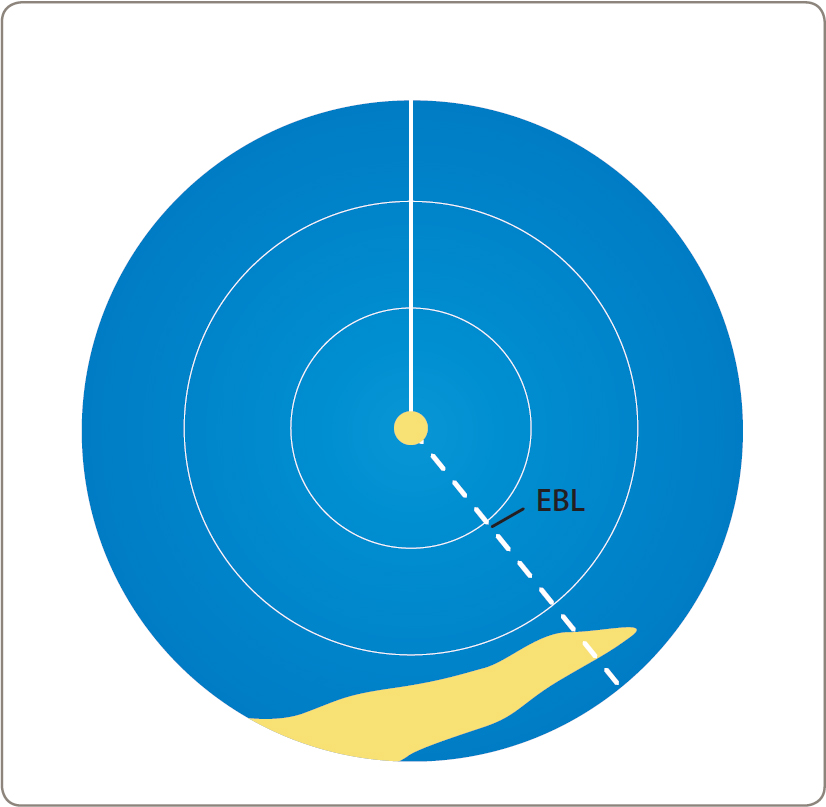
Fig 19.4 The effect of a beam width can be compensated to some extent by placing the EBL about 2° ‘inside’ a headland that is viewed obliquely.
Some sets can adjust their beam width to minimise this effect. If yours cannot, then a width of 4° is a fair assumption unless the handbook states otherwise. If you have no choice but to fix your position by radar bearings only, the same rules apply as to ‘visual’ PLs. Look out for a good ‘cut’, use closer rather than distant objects, etc.
Radar ranges as position lines
As we have seen, radar bearings may be far from accurate. The capacity of radar to determine range, however, is far more refined. Indeed, it is generally good to within ±1% of the range scale in use.
Most modern radar sets have a Variable Range Marker (VRM) which is adjusted electronically by the user to determine distance off an object on the screen. The distance from an object can be plotted on the chart as a circular PL, just like the distance off a rising light. If you can produce three such PLs you have the elements of a three-point fix, which is likely to be very accurate and whose cocked hat can be evaluated as though it were a visual fix (see Fig 19.5).

Fig 19.5 The best radar fix is by plotting the distance of three charted objects. Their ranges are read off the screen by means of the VRM.
Mixed radar fixes
If you need a radar fix and only a single target is recognisable on the screen, you can use the EBL and the VRM on the same object to generate a fix that is geometrically identical to one worked visually from a rising or dipping light. The fix may not be the finest ever, but it should be a good deal better than its visual counterpart. Plot the distance off as one PL on the chart and the bearing as a second, crossing it at right angles. The resulting fix will be as good as the radar bearing you managed to take. If the range is extreme, this may also be misread because the radar cannot see over the horizon down to sea level. You may be taking the range of high ground half a mile inland from what you thought was the headland.
The object in view to the radar in Fig 19.6 has no such problems. It is a racon, which is a radar reactive target marked as such on the chart. This one is a light float. Its compass bearing is 075˚T (ship’s head + relative bearing), its range is 12 miles and the time 0600. This particular racon identifies itself by a flash running radially out behind the object ‘blip’ on the screen. Others may show a Morse code.

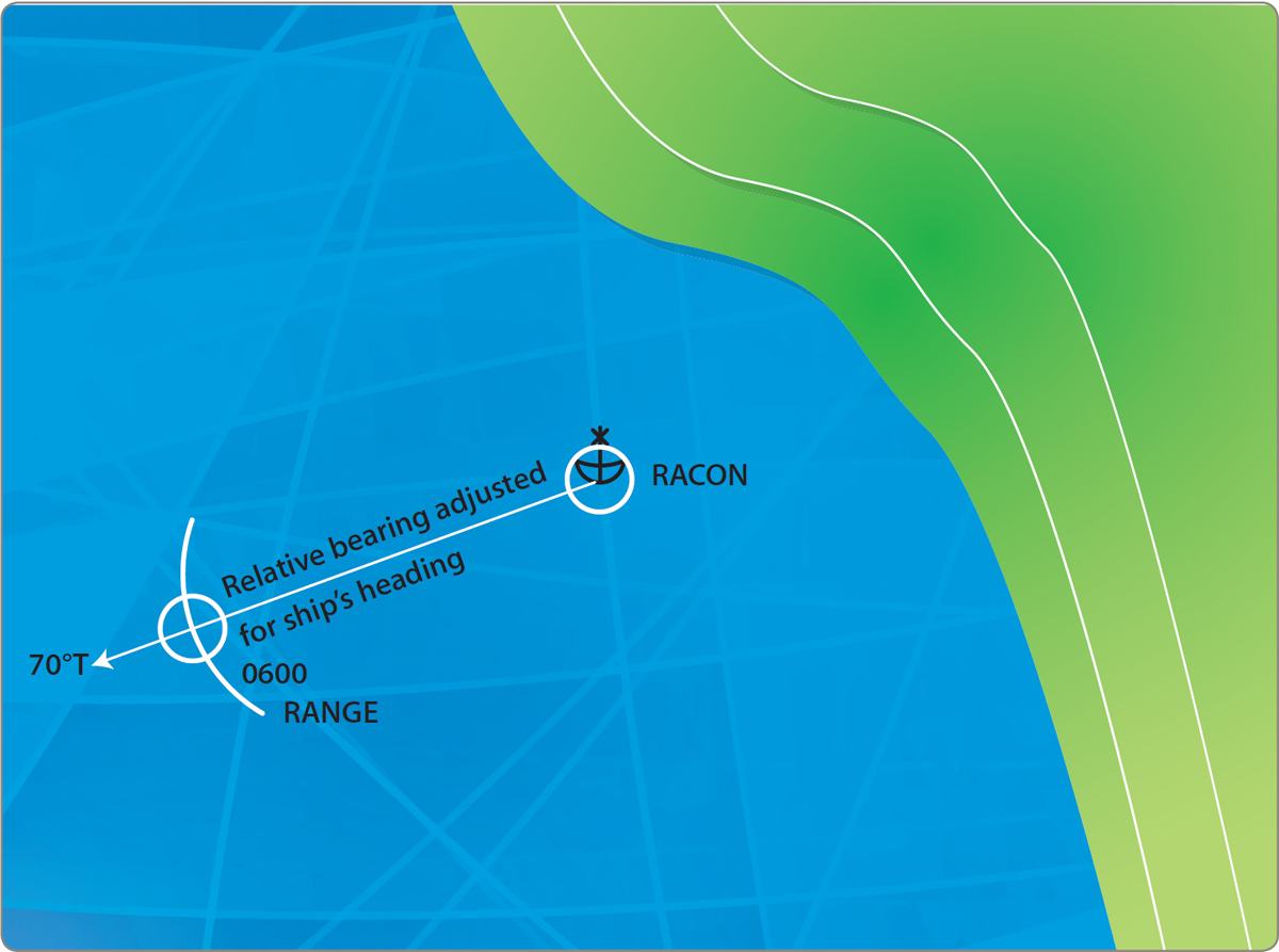
Fig 19.6 A radar fix from a range and a bearing. Note that the racon leaves its ‘mark’ on the radar screen. The upper illustration carries the following:

The illustration below shows the fix plotted on a chart, having extracted the distance from the Variable Range Marker.
Had the light float been in sight, a better fix might have been obtained from a visual bearing crossed with a radar range, thus making the best of both worlds. A third PL from some other source, even if it is only the echo sounder, would have further refined the position.
Radar and other fixing systems
If your yacht is equipped with both radar and GPS, it is possible to navigate in poor visibility while subscribing to the essential maxim that one source of information must always be cross-checked against another. If it is absolutely vital that no mistake is made, perhaps in the vicinity of rocks or other dangers, a GPS fix can be checked against one worked up by radar from ranges, or a range and bearing.
Many modern yacht radars will interface with a GPS receiver. Waypoints can thus be displayed on the radar screen, where they appear as a sort of round lollipop on a stick. This comes in handy, and can be a particular comfort when you are trying to work out which of four or five blips is the buoy you are looking for in busy waters on a foggy day. So long as the boat’s whole electrical system does not go down, you are now in very good shape indeed because you are using information drawn from two independent sources. The GPS data comes from outside the yacht and is beyond your control, while the radar information is generated by the yacht herself from within her own resources. Where they match up, you can be confident that all is well. If they do not, open your log book and click yourself into ‘manual’ mode to find out what has gone wrong.
| SKIPPER’S TIPS | Radar chart overlays |
| Radar displays can come as part of a chart plotter package, which confers the option of viewing either the plotter or the radar. Split screens allow you to view both at once – albeit at a diminished scale, while the truly sophisticated units allow you to view a full-scale plotter chart complete with boat in situ, then overlay the radar scan on to it. This immediately shows which contacts are buoys and which may be ships, how the land is showing up on the radar, and much more. Perhaps the best thing of all is that you can use the overlay to learn how to ‘see’ beyond the blips to understand what the radar is picking up. Use the overlay on a fine day and flick between it and pure radar, looking out with your own eyes at the same time. Next time it’s foggy, you’ll have a far better notion of what your instruments are telling you. | |