7
Compositing CGI

WWW To download the web content for this chapter go to the website www.routledge.com/cw/wright, select this book then click on Chapter 7.

Much of the visual effects compositing today is about compositing CGI (Computer Generated Images) so the modern digital compositor must become familiar with the terminology and techniques for this essential branch of compositing. In this chapter we will look at what lighting passes are, then examine the proper workflows for compositing multi-pass CGI, and which math operators to use for each type of lighting pass. We will also look at AOVs (Arbitrary Output Variables) and their many important roles in compositing CGI. Normals relighting is a very powerful technology for compositors as it allows us to literally relight the rendered CGI images – if we have the necessary AOVs of course.

The OpenEXR file format was introduced in 1999 by ILM and has swept the visual effects industry because it brings important new capabilities to compositing CGI and we need to understand those capabilities. HDR (High Dynamic Range) images are now key players in visual effects and compositing CGI, so we will take a close look at why they are important and how to work with them. And lastly we will learn about Deep Compositing, an incredible new technology that solves entire classes of problems when composting CGI by adding the knowledge of depth to the image file itself.

7.1 Multi-pass CGI Compositing

Rendering CGI is very expensive (meaning compute time here). A sophisticated CGI character can take as long as 24 hours PER FRAME to render. The entire strategy to compositing CGI is based on this crippling rendering bottleneck by moving as much of the workload to compositing as possible. The basic idea is to not only render each object separately but to also render each object in separate lighting passes. The compositor then combines the lighting passes to build up each character, then each character is composited individually in the scene. The huge win here is that if a change is needed (and changes are always needed) rather than firing up the render farm for a week to, for example, increase the specular highlights, the compositor re-comps the shot with the highlights dialed up – in a few minutes.

In fact, the CGI compositing pipeline is evolving to the point where CGI artists often just blast out the lighting passes without fussing over them with repeated re-rendering, then give them to the compositors to dial them in for the finished look during the comp. We like this because it has dramatically increased the contribution and importance of the compositor to the final look of the shot to such a degree that in some corners the job is now referred to as a Lighter/Compositor. Of course, to do this you must first master multi-pass CGI compositing.

Besides the production efficiency of rendering separate layers there is also a huge work-flow advantage. Most of the CGI we composite is over live action. Separating out all of the objects and lighting passes allows for some compositing magic to be applied to the finished scene item-by-item that could not otherwise be done if all objects were rendered as a single image. Besides the obvious issue of color correcting each object individually, other examples would be adding glows, interactive lighting effects, shadow effects, depth haze, depth of field, and many, many other effects that are added during compositing.

7.1.1 Process Verification for Your Renderer

You may have heard many things from many sources about the proper math operators to use for various types of lighting passes. Some say screen, others say multiply, I will say add (sum) in this book. But who to believe? Me, of course, but I offer you an empirical method for determining exactly what is correct for your particular workflow – a process verification for your renderer whether it is RenderMan, Arnold, V-Ray, Mental Ray, Arnold, or any other.

Here’s the idea – when you combine all of the separate passes for a CGI object it should match exactly the same object rendered in its entirety with all passes combined inside the renderer. This criteria cannot be disputed. All CGI renderers work internally in linear float, so obviously your compositing must also be linear float. But what about the math operations to combine the various passes?

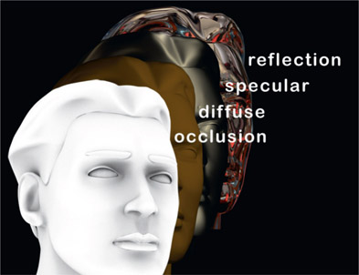
Have the CGI department do a “hero” render of an object with all of the lighting passes combined inside the renderer – ambient, diffuse, specular, reflection, ambient occlusion, etc. This can be a single frame. Then you combine all of the separate passes for the same object and compare it to the hero render. They should match exactly. Forget what you have heard. This is the definitive proof that you have a correct workflow.
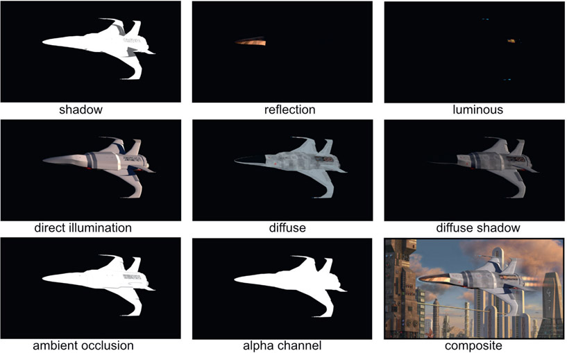
Figure 7.1 Multiple render passes combined into a composite (Space fighter courtesy Tom Vincze)

Figure 7.1 Multiple render passes combined into a composite (Space fighter courtesy Tom Vincze)

7.1.2 Render Passes

Rendering in passes refers to rendering the different surface attributes of a CGI object into separate files so they can be combined in compositing. A CGI object’s appearance is built up with layers of different materials that combine to give it its final look. In so doing the compositor can make adjustments to each layer to control the final look without having to re-render the CGI. If the reflections need to be increased the compositor simply dials up the reflection layer in the composite. The CGI is not re-rendered unless a change is need that is beyond what can be adjusted in compositing. Even then only the render pass in question is re-rendered, not the whole lot.

Figure 7.1 shows just some types of render passes that might be used for the final composite. These are not the only passes and indeed other types of passes could have been created. There is no industry standard list that is always used, and in fact, render passes can be created that are unique to a specific shot. In this example a Luminance pass was needed for the glowing parts of the laser cannon tips and hot engine parts, which would not be needed if rendering non-glowing objects.

There are a great many possible types of render passes, and the breakdown for which passes are needed will vary from shot to shot. However, many vfx studios have their own standard list of render passes that they always output for every shot. If a shot does not need to use a particular pass then the compositor simply ignores it. Particular shots may need some special passes to accomplish some particular effect, so those passes will be added to the standard render list. You might composite one shot using only five passes while the next shot will require 20.

Here are some commonly used render passes and what operation to use to layer them together. There are no industry standards on the types of render passes or their names so there are many religious differences on these points. Be prepared to go with the flow of whatever visual effects studio you are working for. But here are some common ones:

Beauty pass / color pass / diffuse pass – is a full color render of the object with colored texture maps and lighting. It will normally not include the specular highlights, shadows, or reflections, which will be rendered in separate passes then blended with the beauty pass in comp.

Specular pass / highlight pass – all other attributes are turned off and only the specular highlights are rendered. This pass is summed (added) to the beauty pass.

Reflection pass – all other attributes are turned off and only the reflections are rendered. This pass is summed (added) to the beauty pass.

Ambient occlusion – an all-white version of the object with dark regions that is essentially a map of how the ambient light diminishes in corners, cracks, nooks and crannies. It is not a color pass representing light, so it is applied with a multiply operation.

Shadow pass – often rendered as a one-channel image as a white shadow over a black background. This is typically used as a mask for a color correction operation that introduces the shadow to the comp, as well as imparting a color shade to it.

Alpha pass – the alpha channel for the object that carries the transparency information about it and is often rendered as a separate one-channel image, white over black.

7.1.3 Lighting Passes

Lighting passes render each light (or group of lights) separately for each render pass so that the light levels can be dialed in at comp time to provide even more control over the final comp without re-rendering the CGI. This is particularly important when compositing CGI with live action, where the lighting must carefully match the live action scene, plus the frequent need to animate the lighting to respond to changes in the live action. Lighting effects driven by the live action are much easier to animate in 2D than in 3D.
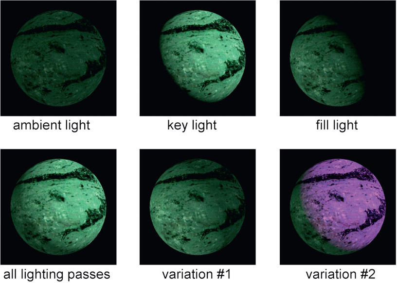
Figure 7.2 Multiple lighting passes composited together

Figure 7.2 Multiple lighting passes composited together

Figure 7.2 shows a simple CGI object rendered with just an ambient light, fill light and a key light. The initial comp of all the lighting passes is shown in the lower left image (all lighting passes). Now, variations of the lighting become very cheap and easy to do with no re-rendering of CGI. In variation #1 the main lighting direction was totally reversed simply by raising the fill light and lowering the key light, and in variation #2 the key light was colored magenta. The point here is that massive changes in the lighting can be made in seconds in comp rather than days in render.

WWW Lighting Passes – this folder contains the three lighting passes from Figure 7.2 that you can comp in your own software with the plus operation. Try some lighting variations of your own.

7.1.3.1 Render Passes Workflow

There are two basic workflows to compositing CGI. The first I call a “bottom up” approach – all of the separate render passes are combined to build up the character from scratch while each pass is individually dialed in for the final look. The second I call a “top down” approach – starting with the beauty pass, other passes such as specular and reflection are then added to it. If a revision to a pass is needed that is already baked into the beauty pass then that pass is backed out, modified and then merged back in. Here are the basic rules:

  • If the render pass represents light (ambient, diffuse, etc.) then it is added (summed) to build up the light layers.
  • If the render pass is lighting information (ambient occlusion, etc.) then it is multiplied.
  • If the render pass is a shadow then it is used as a mask to color correct the background to impart both shadow density and color.
  • If the render pass is an AOV then it is used to modify the composited CGI in some way and its use is totally dependent on what kind of information it holds.

The following example illustrates the “bottom up” workflow for building up a CGI composite by combining all of the render passes for the final comp. It includes which math operators are used for combining common render passes.

WWW Render Passes Workflow – this folder contains the five render passes from Figure 7.3 that you can comp in your own software using the math operations as described.
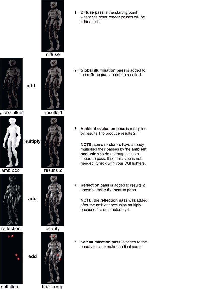
Figure 7.3 Render passes workflow (Mantis model provided by CG Spectrum)

Figure 7.3 Render passes workflow (Mantis model provided by CG Spectrum)

7.1.3.2 Beauty Pass Workflow

This illustrates the “top down” workflow starting with a beauty pass. You might think that starting with the beauty pass, which is already a combination of multiple render passes, might be restrictive because the passes are baked in. Not a problem. If, for example, the diffuse lighting needed to be lowered or colored red, it can be subtracted from the beauty pass to back it out completely, then color corrected and added back in.

Here is a workflow example that starts with the beauty pass then the reflection pass is backed out, color corrected to a deep blue, then added back in:
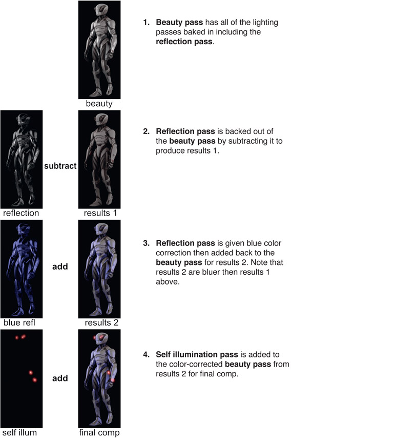
Figure 7.4 Beauty pass workflow

Figure 7.4 Beauty pass workflow

WWW Beauty Pass Workflow – this folder contains the three render passes from Figure 7.4 that you can comp in your own software using the math operations as described.

7.1.4 AOVs

AOVs (Arbitrary Output Variables) are also render passes, but these passes contain data about the scene, not color or light information. A common example would be the depth pass which, for each pixel, contains the distance from the rendering camera imaging plane to the surface of the object. It looks like a grayscale image, but the code values of each pixel represent distances, not color. Again, this AOV is information about the scene, not the scene itself.
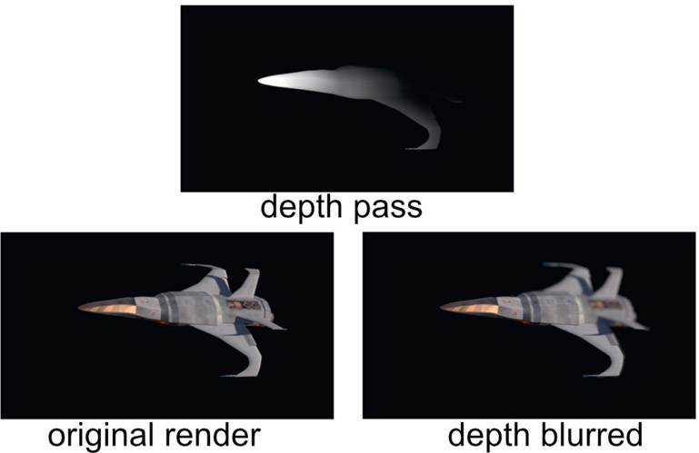
Figure 7.5 Depth of field added to a 3D image using a depth pass

Figure 7.5 Depth of field added to a 3D image using a depth pass

Like many AOVs, the depth pass can be used to add a variety of effects. It might be used to introduce a depth haze to a shot, to control the falloff of a lighting effect with distance, or to control a depth-of-field blur on a 3D object like the example in Figure 7.5. The depth pass contains the depth information, but to use it a tool must be used that understands the meaning of the data and knows how to manipulate the image that the effect is applied to – so we will need a DepthBlur operation. Figure 7.5 shows a depth blur applied to the original render. Note that a depth blur is different than a regular blur. Such distinctions are clarified in Chapter 11: Camera Effects.

Tragically, there is no industry standard yet for the data format for depth information, or for any AOVs for that matter. One rendering software package might define zero black to be infinity and the code values get larger (brighter) as the surface gets closer to the camera. Another may make the opposite determination – where brighter is further from the camera. Perhaps this one defines the data to be absolute distance from the camera, but that one defines it as a ratio of the distance to some reference. This is particularly exciting for us compositors because we may actually be dealing with more than one renderer in a job, each with its own ideas about depth data. It’s a wild and woolly world out there so you will have to know the format of the depth data you are working with and inform your compositing software appropriately. Since the 3D coordinate system assigns Z to the depth axis into the scene, the depth data is stored in the “Zchannel like the alpha is stored in the “A” channel, so some call this “depth Z data”. Again, there are no set standards.

Another commonly used AOV pass is the motion UV pass, shown in the center panel of Figure 7.6. A motion UV pass is a two-channel image containing pixel-by-pixel data on how an object is moving. The motion data for a pixel requires two numbers – how much the object moved in X and how much in Y. The black part of the image is not missing data. It may simply mean the motion is zero (a static object) or it contains negative numbers which appear black in the image viewer. Again, our compositing program must have a tool that both understands the motion data and how to apply it to the image. The original image in Figure 7.6 had the motion UV data applied to it with a MotionBlur tool to produce the motion-blurred image on the right. Applying motion blur this way is vastly cheaper computationally than calculating true 3D motion blur in the render, and also allows it to be dialed in during the comp as well.
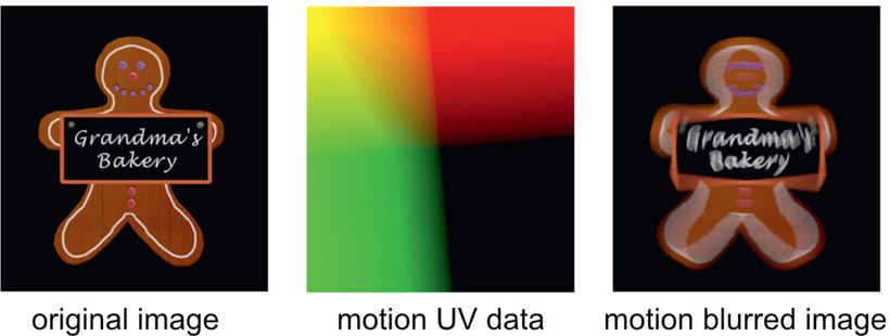
Figure 7.6 Motion blur added to a 3D image using a motion UV pass

Figure 7.6 Motion blur added to a 3D image using a motion UV pass

Like the render passes and lighting passes there is not a standard list of AOV passes that you can learn about and be done with it. There are common ones like the depth Z and motion UV, but data passes can be invented for just about any special problem in production.

7.1.5 ID Passes

ID (identification) passes are masks rendered for specific items within an object that are used to isolate those items for special treatment such as color correcting. Using the car in Figure 7.7 as an example, the side windows may need to be darker and the alloy wheels more reflective. In order to isolate these parts a mask is needed, and that is what the ID passes are all about.

The idea is to give the compositor control over the final color correction of each and every part of the CGI object by providing a separate mask for them. Providing the masks is far more efficient than rendering the object in multiple pieces so each piece can be individually color corrected. Instead, a series of ID passes are rendered, but the interesting thing here is how they are stored in the image file.
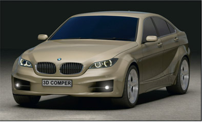
Figure 7.7 CGI object rendered as a single object
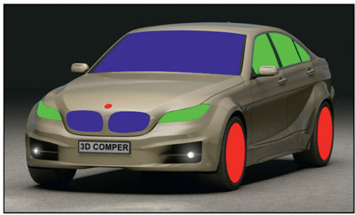
Figure 7.7 CGI object rendered as a single object

Figure 7.8 Matte passes in the red, green, and blue channels
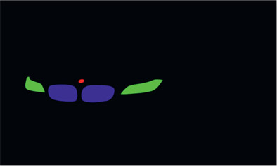
Figure 7.8 Matte passes in the red, green, and blue channels

Figure 7.9 ID matte pass file #1
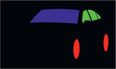
Figure 7.9 ID matte pass file #1

Figure 7.10 ID matte pass file #2

Figure 7.10 ID matte pass file #2

Rather than creating a separate file for each mask it is more efficient to combine several masks into one file. Since a mask is a one-channel image and an RGB file has three channels there can be three masks in each file if one mask is placed in each of the red, green, and blue channels. RGBA files could be used to put a fourth mask in the alpha channel as well.

Figure 7.7 illustrates a CGI model rendered as a single object. Of course, as we saw above, it would actually be rendered with multiple passes. You can imagine the database disaster it would create if the car were rendered in dozens of separate pieces, each with all the different render passes. Figure 7.8 shows a total of six masks that were rendered as three masks in two different RGB files. For this reason some call these RGB masks. Not a very descriptive name if you ask me, so we won’t go there.

Figure 7.9 and Figure 7.10 show what the two ID pass image files look like when viewed individually. The beauty of this arrangement is that you get three masks in each file (four, if the alpha channel is used), the render is cheap (i.e. fast) and the file size is incredibly small. This is because the picture content is incredibly simple, being almost all either solid black or solid white data in each channel, which is very efficiently compressed by a lossless run-length encoding scheme such as LZW compression.

Figure 7.11 RGB channels separated into one-channel masks

Figure 7.11 RGB channels separated into one-channel masks

Figure 7.11 shows the red, green, and blue channels of the ID pass from Figure 7.10 that have been separated into single channels for masking. Of course, the savvy compositor would not actually have to physically separate them into single channels like this because the mask input of an operation can usually be directed to use either the red, green, blue, or alpha channel as the mask.

WWW ID Mattes – this folder contains the car and the ID mattes from Figure 7.8. Try your hand at using them to selectively color correct different areas of the car.
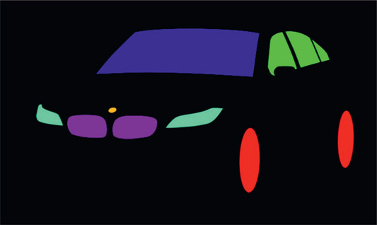
Figure 7.12 An RGBCMY ID pass

Figure 7.12 An RGBCMY ID pass

Some make the mistake of trying to pack more masks into an RGB image by adding CMY masks (Cyan, Magenta, Yellow) like Figure 7.12 that are easy to isolate with a chroma key. Don’t do this. Upon close inspection you will find degraded edges where CMY masks touch or overlap RGB masks. ID masks take very little disk space because they are run-length encoded so there is little gain with this trick. Further, with the use of EXR files (coincidentally, the next section) any number of ID masks may be put in single file so there is no saving in the number of files needed either.

7.1.6 Normals Relighting
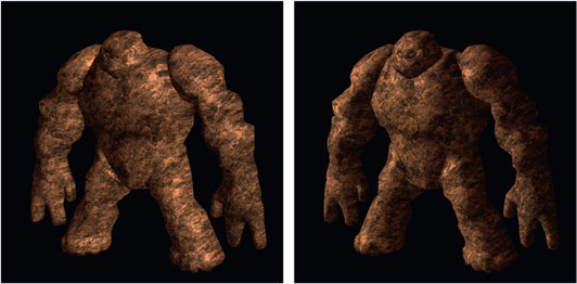
Figure 7.13 Light direction changed with normals relighting

Figure 7.13 Light direction changed with normals relighting

Speaking of AOVs, here is a truly spectacular use for them – a finished CG render can actually be re-lit during compositing. Not just increase or decrease this or that lighting pass but actually pick up the light sources and move them in the scene to light the object from a completely different direction like the example in Figure 7.13. The picture on the left shows the character lit from the right side while the picture on the right shows the same image after normals relighting where the light source has been moved around to the left side. Again, this is done entirely in compositing with no 3D models or rendering. But how is this even possible when working with just 2D images?
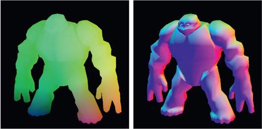
Figure 7.14 Position and normals AOV passes

Figure 7.14 Position and normals AOV passes

With AOVs, of course. Figure 7.14 shows the two AOVs that make the magic happen. On the left is the position pass, which is the original XYZ location in 3D space for each pixel. The AOV on the right is the normals pass, which is the direction that each surface was oriented for each pixel. What exactly surface normals are is explained in Chapter 8: 3D Compositing.

These two AOVs give the compositing software the location in 3D space of each pixel and its orientation. Add to this information the original 3D camera and light positions and the normals relighting tool can calculate how that surface would be lit. The lights in the compositing software can then be repositioned and the normals relighting tool will calculate the new lighting for the object. A CGI object that took days to render can be relit in minutes. This is a dazzling illustration of the power of the industry trend to do things in 2D rather than 3D. Does your compositing software have a normals relight tool?

As if the amazing power, flexibility and speed of AOVs were not enough, the real kicker is that they are also practically free. The reason is that the 3D rendering software has to calculate these AOVs internally anyway as part of their normal internal math operations. All we need to do is ask the 3D renderer to write them to disk instead of discarding them. To be sure there are other AOVs that can be rendered that the 3D software did not need, so they would add slightly to the rendering overhead. But the point here is given the information about the original 3D scene that AOVs represent, modern compositing software can do some amazing things. But more importantly, they can do them in seconds, not days. And in the world of visual effects, speed is life.

There is another spectacular use of AOVs where the 2D images are used to create to a 3D point cloud of the character for 3D lineup. But that will have to wait for the next chapter.

7.2 EXR File Format

In 1999 ILM gifted the world of visual effects by releasing their OpenEXR file format free to the entire industry. It has a number of features specifically designed to support the compositing of high-end visual effects shots. All major 2D and 3D software packages support it and it is the primary file format used in production for visual effects studios, both large and small, so it is by far the most important file format in the industry. Here we will learn why. Here are some of the features that make EXR files so important:

Tiled images – this is essential for reading in texture maps for CGI rendering.

Multi-views – stereo left and right views are supported, plus the user can define any number of additional views.

Deep images – native support for deep images are the subject of Section 7.4: Deep Compositing below.

Metadata – full support for all metadata, plus the ability for users to define their own metadata.

And these are the little things. Here are the big things:

7.2.1 Film Scans

First of all, EXR was carefully designed to hold high-resolution film scans at incredible precision and unlimited resolution. It supports a lossless compression for film scans that can cut the file size in half. Floating point is essential for precision but the standard 32-bit float would make the file sizes too large, so the EXR file format’s native data is 16-bit half float. This allows for a huge range of data values from negative to positive with incredible precision. Further, the precision actually increases as the values approach zero, which is where most of the image data is (most film scan data will range between 0 and 10 or so), and loose precision towards very large numbers where you don’t need the precision anyway. It’s just brilliant!

While 16-bit float is awesome for storing image data it has insufficient precision for processing. During heavy processing round-off errors could accumulate so all systems read in the 16-bit float and immediately “promote” it to 32-bit float which has all the precision anyone could ever hope for.

7.2.2 Linear Lightspace

The EXR file format is, by definition, a linear image format. Other film file formats such as Cineon and DPX support log data. Tif, TARGA and PNG are gamma corrected linear data. EXR is explicitly linear. And this is in keeping with the industry trend of moving all image processing for visual effects to linear. See Chapter 12: Digital Color for a complete discussion of linear space and why it is the only way to comp.

7.2.3 Arbitrary Image Channels

The explosion in separately rendered elements for CGI images resulted in a matching explosion in the number of files needed for each frame of the composite. If a single object had 12 render passes, 3 data passes, and 5 matte passes the compositor was staring at 20 input files for that one object because many file formats only hold one image, or render pass. A very small example is illustrated in Figure 7.15, where only four render passes are stored in four tif files.

Figure 7.15 Four tif files with single render passes

Figure 7.15 Four tif files with single render passes

Figure 7.16 Single EXR file with multiple render passes

Figure 7.16 Single EXR file with multiple render passes

Then along came ILM with their OpenEXR file format to rescue the industry from a tidal wave of tif or png files. While the EXR file format has several important virtues, the one most germane to this discussion is that it is designed to hold multiple images in one file. Figure 7.16 illustrates how the four render passes are all contained in one EXR file. You can think of the different passes like the layers in a Photoshop file. Just like the Photoshop file, within a layer there can be several channels such as RGBA, as well as others. Even AOV passes can be contained along with the images, mattes, masks, vectors, or whatever. In fact, the user can define any number of layers and channels in an EXR file making it ideal for multi-pass CGI compositing. Referring to the ID mask discussion above, a single EXR file could have, for example, 27 ID masks. Better yet, the EXR file format allows each channel to be uniquely named, so the 27 ID masks might be named “tire”, “headlights”, “bumper” etc. Virtually all 3D animation programs now write out an EXR file, and almost all paint and compositing programs will read them in and display the names of each channel.

7.3 HDR Images

One of the main reasons for working on float is the need to work with HDR (High Dynamic Range) images, which are used extensively in the production of visual effects. In this section we will take a look at what HDR images are and how they are used.

Figure 7.17 An HDR photograph (Courtesy ILM)

Figure 7.17 An HDR photograph (Courtesy ILM)

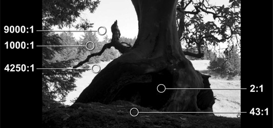
The real world, of course, is high dynamic range meaning that the brightest part of a scene can be thousands of times brighter than the darkest. Figure 7.17 shows a black-and-white HDR photograph with selected regions marked with their brightness relative to the blackest pixel in the picture. The camera is actually shooting into the shadows but daylight portions of the background are in frame, making it a very high contrast scene. As you can see, the sky is nine thousand times brighter than the blackest pixel. If this scene were shot with a conventional camera rather than an HDR camera, virtually the entire daylight background area would be blown out and clipped to 1.0.

Early cameras were what we might categorizes as Limited Dynamic Range (LDR) so they could only capture images up to a certain point in brightness. Any scene content brighter than the camera’s maximum exposure range would be clipped to its maximum code value. As a result, the specular highlights and light sources such as fire, explosions, and light bulbs were clipped at some value far below their true brightness. We are talking about cameras that could only capture maybe 6 or 7 stops of dynamic range, meaning the brightest part of the LDR picture could only be one or two hundred times brighter than the darkest part. Since this was the most the cameras of the day could manage the vfx pipeline did not need to do any better so we used LDR software, which limits code values to between 0 and 1.0, which was fine for video. Of course, 35mm film was the first class of HDR images because it could capture 10 stops. And modern digital cinema cameras claim much more than 10 stops – with varying degrees of veracity.

Figure 7.18 Some HDR code values

Figure 7.18 Some HDR code values

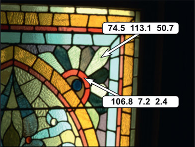
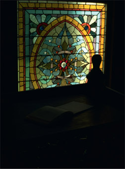
Figure 7.18 shows an HDR image with code values far above 1.0. This image is a close-up of the one shown below that has been “normalized” to between 0.0 and 1.0 so we can view it in print. If the software does not work in float these HDR code values will all get clipped to 1.0. The damage this causes is demonstrated starting with Figure 7.19, which shows the full original image from which this close-up was taken. If the HDR image is read into LDR software then all codes values above 1.0 get clipped to 1.0. The results of that are shown in Figure 7.20, where the image has been clipped then darkened down to show the damage from clipping. When the image gets clipped all of the clipped pixels take on code value 1.0, but when darkened all of the clipped pixels will have code value 0.5, for example, the flat slabs of gray seen in Figure 7.20. Figure 7.21 shows the original HDR image darkened down using HDR software that does not clip the code values. As you can see, all of the highlight detail and color has been retained.

Figure 7.19 Original image

Figure 7.19 Original image

Figure 7.20 Clipped and darkened

Figure 7.20 Clipped and darkened

Figure 7.21 Not clipped and darkened

Figure 7.21 Not clipped and darkened

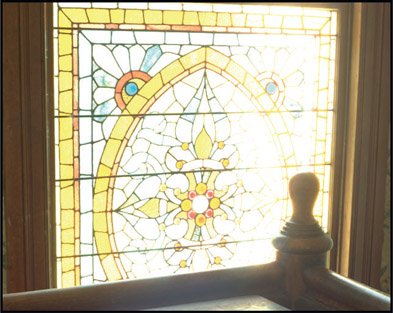
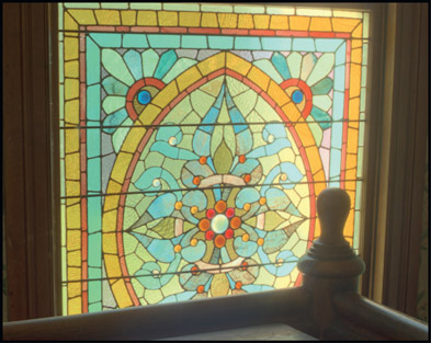
So, what outcome does all this have on compositing visual effects? If the software clips the HDR images like in Figure 7.20 and the shot is going out to video, which is an LDR medium, the results would look like Figure 7.22. However, by using HDR software we can preserve the highlight detail and perform a soft clip to bring the HDR image down to within video limits, so that the stained glass window could look like Figure 7.23. Which would you rather have in your comp? More to the point, which would the nice client want?

Figure 7.22 Hard clip in an LDR system

Figure 7.22 Hard clip in an LDR system

Figure 7.23 Soft clip in an HDR system

Figure 7.23 Soft clip in an HDR system

Further, if the HDR stained glass window were clipped in an LDR software package and then color corrected darker, the clipped region would be all gray and icky like in Figure 7.20. But the big issue today is not video, but cinema. The theaters are projecting HDR images so the shots we deliver for theatrical projection must also be HDR.

The impact of HDR images is actually much more important for our friends in the CGI department because they need to use HDR images for their lighting models. Note that the internal math for all CGI renders is HDR linear float, so their rendered images can have code values far above 1.0. You could very well get CGI rendered for video with code values above 1.0, so you will need to know how to protect your images with soft clipping. This is covered in Chapter 10: Sweetening the Comp.

7.4 Deep Compositing

Deep compositing was born out of a need to cut down on the amount of CGI rendering for highly complex scenes as well as to solve the layering complexity problem and the depth-compositing edge problem. Deep compositing refers to compositing a vfx shot using deep images. So what are deep images? They are CGI renders that have vastly more information stored with each pixel, which imbues the image with a certain intelligence about the shot. So we will start with what deep images are.

7.4.1 Deep Images

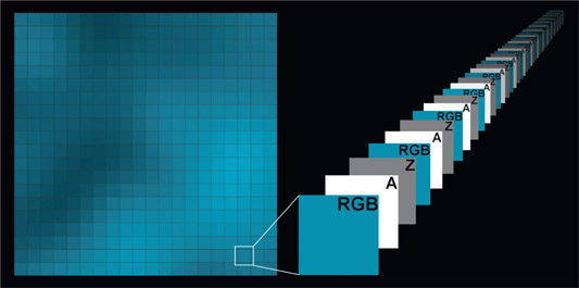
Before we can understand deep compositing we have to be clear on what a deep image is, but for the purposes of this discussion let us refer to convention CGI images as “flat”, to distinguish them from deep images. For each pixel, conventional flat CGI images will have RGB channels for the color, an alpha channel which sets the transparency of that pixel, and may have a depth Z channel to set that pixel’s depth in the 3D scene. As we have seen in the discussion above, additional data channels can be associated with each pixel such as surface normals, motion UV, and others, but the point here is that there is only one set of channels which are shared by all the pixels in the image. Another way to say it is that every pixel in the image will have the same number of channels.

Figure 7.24 Deep image multiple pixel data sets

Figure 7.24 Deep image multiple pixel data sets

Deep images, on the other hand, have multiple sets of data associated with each pixel as illustrated in Figure 7.24. One pixel of the image has been marked and expanded to show the multiple data sets “behind” each pixel. There are multiple sets of RGB, A, and Z channels all stacked on top of each other for every pixel in the image. Each sample represents a different color, transparency, and depth value for that one pixel so all pixels can be thought of has having a “thickness”. Further, each pixel in the image will have a different amount of depth data depending on how “thick” that pixel is. One pixel may have three depth data sets while the pixel next to it may have 10. Again, “flat” images have the same amount of data for each pixel.

If we are rendering the solid surface of a car fender for example, then the deep image render would only have one layer that represents that single hard surface and would be for all intents and purposes just a flat image. But consider if that car fender was moving away from the camera. During the camera’s open shutter time that hard surface is actually located within a range of distances from the camera. With a flat image render we must pick a single instant to represent a single depth from the camera. With a deep image we can bundle several depth samples for that pixel, which span the entire open shutter time. You can think of it as “temporal anti-aliasing”.

There are other CGI scenarios where a single value for the color, transparency and depth are inadequate. Consider a fog bank. When rendered as a flat image we would end up with a single value of fog for each pixel, but in actuality the fog pixel we see rendered is the result of light traveling from deep within the fog. This is the essence of volumetric objects such as clouds, smoke, fire, fog, and even hair. They don’t have a single hard surface that you can point to and say that that is the pixel value for the entire volume. It is in fact made up of many particles that penetrate deep into the fog bank and the final rendered pixel value of a flat pixel is the result of all the internal volume lighting accumulated into a single pixel value – like a single grand total. Deep images capture that same volumetric information with multiple samples at various depths.

But now we have to answer the burning question – so what? What is the value of all this extra data, and to what use can we put it that will justify the shocking increase in rendering time and disc space? A flat 2k EXR image will have a file size of around 10MB. The same deep 2k image could be 100MB – or more. So deep images are very expensive and will only used where they really pay off. They pay off in three ways – the layering complexity problem, the depth edge problem and the re-rendering problem.

7.4.2 The Layering Complexity Problem

Figure 7.25 The layering complexity problem

Figure 7.25 The layering complexity problem

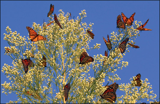
Consider the layering complexity problem illustrated in Figure 7.25. Suppose you had to composite a dozen CGI butterflies, all darting and flapping around, into the CGI bush shown here. On frame 1 butterfly 17 is in front of branch 8, but on frame 12 it hops behind it, then on frame 31 it flies away in front of branch 22 but behind branch 23. Continuously flip-flopping the layering order for all these darting objects becomes a hopeless task. And what if there were 1,000 butterflies?

Deep images solve this hideous layering complexity problem with remarkable élan. Each deep pixel of the butterfly and bush renders knows where it “lives” in the 3D scene. The deep compositing operation simply sorts all the pixels in Z as it layers the two images together. The intelligence of who goes where resides in the pixel data so the compositor no longer has to deal with it. “But wait!” you say. “We can just do a depth composite. Problem Solved.” Not quite. This brings us to the depth edge problem.

7.4.3 The Depth Compositing Edge Problem

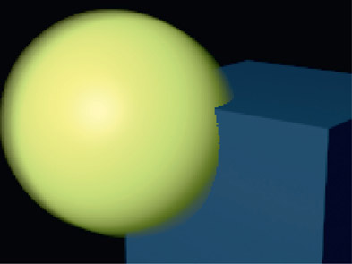
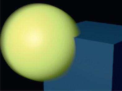
The depth compositing edge problem is that simply using the depth Z data of a flat image to composite two overlapping objects has hideous aliased edge artifacts as shown in Figure 7.26. Here, a flat motion-blurred sphere is penetrating a solid object using a standard depth compositing operation and you can see that the intersecting edge has a horrible case of the jaggies because the depth Z data is not anti-aliased. Each flat pixel contains only one depth value so the compositing algorithm has to make a binary choice – is this pixel in front or behind its opposite pixel? Simple depth compositing is far too crude for our mega-million dollar blockbuster movies. When you read about depth compositing problems like this you will find them also offering all sorts of tips and tricks for blending/blurring/smearing the jaggy intersections between the objects.

Figure 7.26 Conventional depth composite with a flat CGI render

Figure 7.26 Conventional depth composite with a flat CGI render

Figure 7.27 Deep composite with a deep CGI render

Figure 7.27 Deep composite with a deep CGI render

Now consider the deep image composite in Figure 7.27 with exactly the same 3D geometry, materials, and lighting. The only difference is that the CGI was rendered as a deep image then a Deep Composite was done to merge the two layers. The deep sphere’s motion-blurred edges contain multiple depth samples spanning multiple instances of time – that “temporal anti-aliasing” mentioned above. The intersecting edges are now beautifully blended in a very natural way. And again, no operator intervention. The pixels sorted themselves out auto-magically.

7.4.4 The Re-rendering Problem

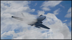
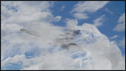
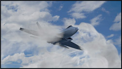
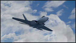
Figure 7.28 Composite of CGI jet and cloud

Figure 7.28 Composite of CGI jet and cloud

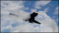
Figure 7.29 Jet holdout for clouds

Figure 7.29 Jet holdout for clouds

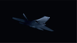
Figure 7.30 Clouds holdout for jet

Figure 7.30 Clouds holdout for jet

To be honest, the two virtues of deep compositing shown so far – layering complexity and jaggy depth compositing edges – were not the prime motivations for developing deep compositing. The real reason was to cut down on rendering time for massively complex CGI scenes.

Figure 7.28 represents a simple composite of a CGI jet with a CGI cloud. Rendered as flat images, the particle system cloud layer would be rendered with a holdout for the jet shown in Figure 7.29 and the jet would be rendered with a holdout for the clouds shown in Figure 7.30. These two flat images would then be composited with a simple Over operation – and we are done. Until the director decides to shift the position of the jet a bit. Now both the jet and cloud layers have to be re-rendered because the holdouts don’t work with the new positions. Then the director decides to shift the clouds – re-render everything. Then the director decides to reposition the jet again – re-render everything once more. You get the picture.

Now scale this story up to the all-CGI jungle scenes of Pandora in the film Avatar with literally billions of polygons and mind-boggling render times, then add in the all-CGI characters. They realized that Avatar would never be released in this century unless something could be done about the massive re-render problem.

Figure 7.32

Figure 7.32

Enter deep compositing. Now consider the three composites in Figure 7.31 through Figure 7.33 showing the jet at three different depths in the cloud. As a flat composite the clouds and jet would have to be rendered three times. With deep compositing the deep images were rendered once then told to move themselves up, down, in or out with simple deep transformation operations during compositing. The pixels sorted themselves out automatically during the deep composite and we got all three versions without re-rendering anything.

Such is the power of deep composting. However, it comes at a steep price because deep renders take much more compute time, disk space, and file transfer time than flat images. But once rendered, they can be endlessly repositioned, even scaled, cropped and color corrected without any re-rendering. For scenes of great complexity it is well worth it. However, you will only see deep images and deep compositing for the money shots of million-dollar blockbuster movies for some years to come. But the march of technology and the speed of machines will get ever faster, making deep compositing more practical over time until they make their way into the mainstream of visual effects.

7.4.5 Deep Compositing with Live Action

But what about deep compositing CGI with live action plates? The answer is simple – a deep image map needs to be created for the live action plate. The deep map is combined with the RGB layer of the live action to make a deep background plate, then the entire shot gains all the advantages of deep compositing. It is relatively easy to paint a deep map for a static image, but if there is a lot of motion in the live action then the task becomes more challenging.

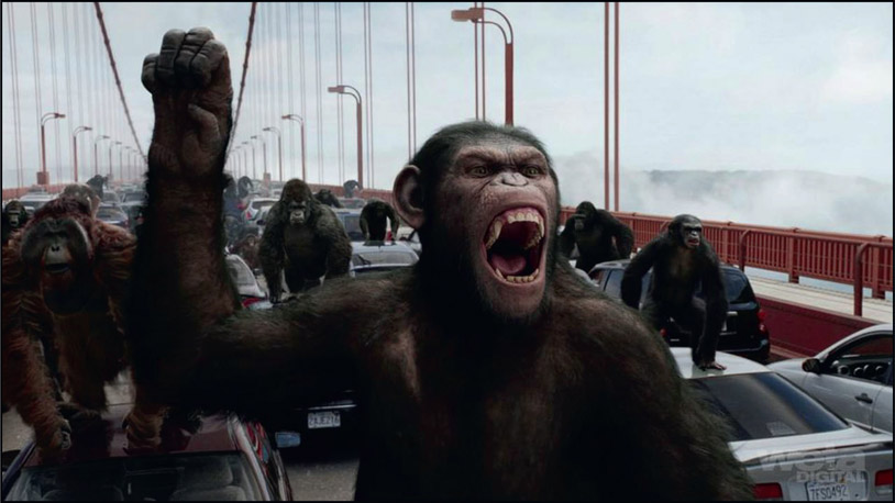
Figure 7.34 Deep compositing with live action (© 2011 Twentieth Century Fox Film Corporation. All Rights Reserved.)

Figure 7.34 Deep compositing with live action (© 2011 Twentieth Century Fox Film Corporation. All Rights Reserved.)

The Weta Digital shot in Figure 7.34 from Rise of the Planet of the Apes is the poster child for deep compositing. This single shot embodies all of three virtues of deep compositing:

Incredibly, there is a technology on the horizon that will eventually allow us to shoot deep live action plates, and that is light field cinematography. Light field cameras capture deep information about a scene and as of this writing there has been one prototype light field cinema camera built and demonstrated. One can envision a future vfx film shot with a light field cinema camera so that all of the effects shots could be done with deep compositing. Read all about it in Chapter 15: Digital Images.

The next chapter moves on to 3D compositing – setting up true 3D environments to re-photograph live action elements. We will see why adding 3D to our compositing allows us to do whole new classes of effects like placing 3D objects in 2D scenes, or 2D objects in 3D environments, set extensions, and many more. For the compositor unfamiliar with the world of 3D a short course in 3D is included.