3
Aquaculture Systems Design
Igor Pirozzi, Paul C. Southgate and John S. Lucas
3.1 Introduction
The primary objective of aquaculture system design is to ensure that a facility is productive in a reliable and cost‐effective manner. The design of an aquaculture system must allow for maximal growth and survival of the target species and optimal market price for the product. Aquaculture systems must also be reliable and cost‐effective to construct, and, from an operator’s perspective, the system should have minimal operating and maintenance requirements. An appropriate design needs to:
- meet the target species requirements;
- allow flexibility;
- provide for low‐maintenance inputs;
- allow for the use of inexpensive materials without compromising quality;
- incorporate back‐up systems where possible; and
- allow for future expansion.
Aquaculture systems vary immensely (outdoor ponds, indoor tanks, sea cages, long‐lines, etc.), but similar forms of aquaculture production have facilities in common. For instance, a semi‐closed tank or pond system will include:
- water supply;
- culture structure;
- aeration;
- power;
- buildings; and
- layout.
Within the above constraints, the final system choice and design, as always, is a balance between species and user requirements, available capital for construction and site constraints.
3.2 Site Selection and Development
One of the most critical considerations for an aquaculture enterprise is choosing the most appropriate site. The site will of course depend on the type of aquaculture being proposed; land‐ or sea‐based, hatchery, grow out etc. and the type of species that is to be cultured. Aquaculture as we know is the farming of aquatic organisms, therefore access to good‐quality water, consistently and reliably, is imperative. If possible, consider sites that already have access to basic infrastructure such as roads and power to reduce initial set‐up costs.
3.2.1 Water Flows
Apart from ensuring the quantity and quality of water available to the system, the distribution of water around the site must also be considered. It is generally appropriate to utilise the shortest routes for water delivery and removal to save capital costs and, if piping is used, to reduce pressure losses due to friction and therefore pumping costs. In addition, it is preferable that the water supply system be controlled from a central point. In a pond system this may be as simple as being able to turn the water supply to a pond on or off without travelling to the pump house. Where possible, water flows to tanks, raceways and ponds should be able to be adjusted individually.
3.2.2 Use of Existing Topography: Water Head/Pump Capacity
All requirements of the farm are important when considering the topography. Topography can be utilised to reduce pumping costs, collect and store water from natural watersheds and provide sites for buildings.
‘Water head’ is the ability or the potential for water to fall, i.e., water will drop from a higher point to a lower point through gravity with no requirement for pumping. The provision of pumping is expensive in terms of both capital construction and running costs. It is important to use water head efficiently in farm design. If using ponds or raceways, the design must utilise the slope of the land so that water may be supplied and drained or drained by gravity, i.e., let the water ‘fall’ down rather than pumping it up. The greater the height that water must be pumped and the greater the distance of piping, the greater the operating costs without improving productivity.
3.2.3 Utilisation of Land and/or Water
As land or water is generally expensive to purchase or lease, it is important to minimise non‐productive space wherever possible. Minimisation of wasted space is as important for recirculation systems as it is for pond farms or marine leases. In general, it is considered prudent to minimise the distances between culture structures (ponds, tanks, raceways, long‐lines) and working areas and buildings.
However, although it is important to minimise unproductive space, there must be sufficient working space to allow:
- access to culture structures and pipework for routine activities;
- vehicle access to work areas;
- pumps and treatments systems for maintenance and adjustment for routine work (e.g., repairing equipment and cleaning/drying nets) and non‐routine work or emergencies to be conducted;
- animal husbandry (e.g., grading) and product processing (e.g., harvesting, slaughtering, packing); and
- a buffer zone around the aquaculture facility, including an ‘environmental protection zone’.
It is important to locate harvesting and processing facilities as close as possible to the harvest site. This will minimise transport requirements, but more importantly it will aid in maintaining product quality, especially in hot climates. However, processing facilities must be kept away from hatchery facilities to prevent contamination of the hatchery area by diseases from the on‐grown stock.
Apart from the areas directly related to growing the product, areas for the delivery, storage and handling of goods such as feeds, fertilisers and chemicals must be considered. Thus, road design must meet all access requirements while minimising construction costs. Consideration must be given to the loads entering and exiting the property as well as the types of vehicles used. Although small vehicles may be used on the farm, transport companies, e.g., feed companies, may deliver using much larger vehicles. When deliveries are purchased in bulk, sufficient space must be available to store and handle the goods. In conjunction with access it is important to ensure that the working yard and turning area for the delivery of bulk supplies and the transport of harvested product is sufficient.
Expansion is often the target for aquaculture ventures, and the ability to expand facilities and operations beyond the initial development must be considered during the site selection and layout design. Where possible, adjacent land or water or land and water must be available to lease or buy in the future. Alternatively, if land or water is cheap enough, it can be purchased to allow for future expansion. The site must be engineered so it can be easily modified for increased capacity. For example, consider using larger pipes initially to avoid replacement costs later.
Although it may be thought of as ‘unproductive space’, a ‘buffer zone’ may be required as part of the licensing requirements from environmental agencies for some forms of aquaculture. A buffer zone around a pond farm may be required as protection against escapees, predators and vermin. Spare ground is also needed for disposal of the pond substrate wastes between crops. In seacage and high‐biomass bivalve aquaculture, e.g., mussel rafts, there is the potential for heavy fouling of the benthos beneath the facilities. Pollution can be minimised if the cages and rafts can be moved to new areas within the lease.
3.2.4 Minimising Construction Costs
When constructing buildings of similar grades, it is generally cheaper to build larger buildings and then divide them into smaller sections and rooms. However, one needs to consider which activities can be conducted within close proximity to each other. Similarly, larger ponds are cheaper to build per unit area than smaller ponds. The manageable size of the pond, however, and the optimum size for growth performance of the cultured species must be considered.
The specification of buildings (i.e., the strength and sizing of materials) and pond walls (i.e., wall height, width and internal and external slopes) is also important. Costs of construction increase rapidly if over‐specification occurs. As such, it is important to consider the appropriate specifications for the required tasks.
3.3 Aquaculture Systems
Owing to the great diversity of aquaculture operations, the description of types of aquaculture systems may be complex and sometimes confusing to the novice. Usually culture systems are classified according to three criteria.
- Type of culture structure. Culture structure describes what encloses or supports the aquaculture organisms. Broadly, aquaculture structures include ponds, tanks, raceways, cages, pens, racks, long‐lines and floats.
- Water exchange. Water exchange describes the amount of water exchanged or the control over water flow to the system. Broadly, the levels of water exchange are static, open, semi‐closed and recirculating (closed).
- Intensity of culture. Intensity of culture reflects the number of aquaculture organisms per unit area or water volume and also the ability of the natural productivity to support the crop. Broadly, the intensity of culture is described as intensive, semi‐intensive or extensive which are detailed in Chapter 2.
The type of system used for aquaculture production is a combination of the above criteria. For example, there may be a pond system that is
- extensive and static: to grow major carp in ponds in China and India;
- semi‐intensive and semi‐closed: to grow silver perch in ponds in Australia;
- semi‐closed and intensive: to grow shrimp in ponds in Asia and the Americas; or
- open and intensive: to grow Atlantic salmon in sea cages in Norway and Canada.
Although a particular kind of system will be considered under each heading, one system is rarely used for the whole lifespan of a cultured species, except in some extensive culture systems. For example, the intensive culture of a particular fish species from gametes to harvest may successively involve the following:
- a small fertilisation tank;
- an embryonic development tank with gentle flow‐through of water;
- a larval tank with gentle circulation;
- a fingerling tank with gentle flow‐through of water;
- a pond for growth of fingerlings to large juveniles; or
- a cage for grow‐out to harvest.
3.3.1 Ponds
Ponds are broadly defined as earthen impoundments for holding aquatic species. Ponds are the oldest aquaculture structure because of the simplicity of basic pond culture in freshwater. Pond culture can be undertaken with nothing more than convenient natural ponds. Purely harvesting from natural ponds is not aquaculture – it lacks the component of enhancing production; but enhancing production may involve nothing more than adding crude organic fertilisers (section 9.7) or removing predators or competitors of the cultured species.
A pond may be a simple hole in the ground (sunken pond) or an enclosed waterway in a valley or stream bed where only one or two walls are constructed (barrage ponds), or it may be above ground (embankment pond). Embankments may also be used to divide a large freshwater or brackish water mass into adjacent subunits, e.g., ponds of varying shapes according to the natural topography. Embankment ponds may be any size or shape, but rectangular ponds are most common as they limit wasted space between ponds. Ideally, water input and discharge from ponds are facilitated by gravity to minimise construction and operating costs. Ponds are most commonly used for culture of fish and crustaceans.
Cheap simple ponds are the most widely used freshwater and brackish water aquaculture systems. The main requirements for ponds are:
- a reliable supply of good‐quality water (preferably gravity fed);
- relatively impermeable soils for construction;
- well‐structured soils with good organic matter content to support pond ecosystems; and
- gravity drainage.
Ponds in general are cheaper to construct per unit area than the cost of tanks and cages, and may be inexpensive to run, depending on pumping costs. Ponds tend to have the lowest stocking densities of the culture structures; however, density varies according to whether the system is extensive, semi‐intensive or intensive (section 2.2). Ponds are generally maintained with a light algal bloom to minimise water exchange.
3.3.1.1 Pond Site Requirements
Assessment of the soil is a very important consideration in aquaculture pond site selection, development and management. It is the soils at the site that will determine the natural productivity of the pond, water‐holding capacity, fertilisation requirements, water quality and construction.
Poor site selection will result in ponds that cannot be managed to suit the requirements of the cultured animals or that require an unacceptable level of inputs and maintenance to do so. The main soil properties important for aquaculture use are:
- physical: texture, strength, stability, water‐holding ability;
- physicochemical: ion exchange capacity, acid–alkaline reaction, leaching effects and absorptive/binding capacity; and
- biological: organic matter and nutrient transforming biomass.
More information on the properties of soil is available from texts on aquaculture pond construction (e.g., Boyd, 1995; Boyd and Tucker, 1998).
In some circumstances, particularly with small ponds and in areas where the soil is porous, the ponds may be lined with impermeable sheeting, e.g., thick plastic sheeting. Soil or another substrate (e.g., sand) may then be added to these lined ponds to provide the functions of soil.
3.3.1.2 Pond Layout
In large pond farms, there is a carefully planned layout of ponds and embankments to include channels between ponds for inflow of new water and outflow of effluent water. There may be tens to hundreds of ponds on a large farm, with the surface area of each pond ranging from ~0.5 to 10 ha (Figures 3.1, 5.4 and 5.8).
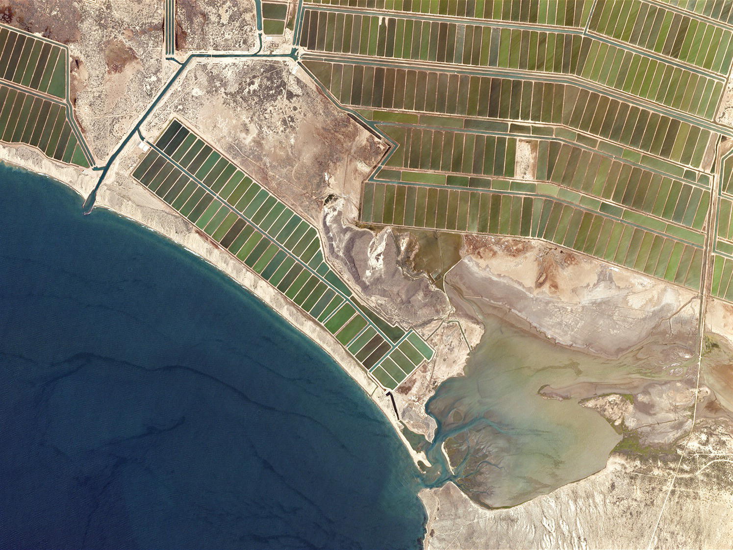
Figure 3.1 Multiple rows of shrimp ponds in a large aquaculture farm in the Gulf of California, Mexico. Note the complex reticulation system from the intake, lower right, to the discharge pipe on the left.
Source: Reproduced with permission from Planet Labs, Inc.
Historically ponds have been constructed in one of the following four main configurations or layouts, each with its advantages and disadvantages. Of these, the Parallel layout is commonly utilized especially in large modern commercial enterprises as it provides the greatest control over individual ponds (Figure 3.1).
- Series. Ponds are constructed consecutively so that water flows through each pond prior to its discharge. This layout allows easy movement of stock from one pond to another and maximal use of water. A disadvantage of constructing ponds in series is the decrease in water quality through consecutive ponds and the inability to isolate individual ponds, preventing the isolation of disease.
- Parallel. In a parallel pond layout, water is distributed from a common supply channel into each pond individually. Effluent water is collected into a common drainage channel. Stock movement is more difficult and water use increases; however, this is offset by greater control over the water exchange for individual ponds and simpler water quality management.
- Radial. Constructing ponds in a radial design is uncommon and is only employed when there is a specific production planning purpose. In a radial layout, ponds are constructed so that each inner pond feeds into multiple outer ponds or larger outer ponds in a concentric pattern. This pond layout may be employed when there is a continual supply of smaller animals (e.g., fingerlings) and, as the animals grow and require more space, they are moved to the outer ponds until they are eventually harvested.
- Inset. In an inset pond layout, one pond is placed inside another larger pond. This method is used when a nursery pond(s) is set inside a grow‐out pond.
3.3.1.3 Pond Size and Shape
Ponds are usually rectangular to allow maximal utilisation of land. Typically, the length to width ratio is 2–3:1. The factors governing the size of the pond are the biological requirements of the culture animals and access to the pond for husbandry. For example, if a pond is to be harvested by seine netting then a recommended maximal width is 20 m. Similarly, 20 m is about the maximum reach of many feed dispensers. If, however, the cultured animals come to the edge to feed and can be harvested using a collection sump, the pond may be much larger. A disadvantage of larger ponds with greater biomass and higher feed inputs is that they may be more difficult to manage.
Probably the greatest disadvantage of a rectangular pond is poor water circulation. Circular ponds have been trialed for high‐value intensive crops with good results; however, the trade‐off is less pond area per unit farm area (Wyban and Sweeney, 1989). Square ponds may permit more efficient use of space as well as facilitate good water circulation and they have been used successfully for shrimp aquaculture (Figure 3.1, Figure 3.2); however square layouts may not be as effective for some species of finfish.
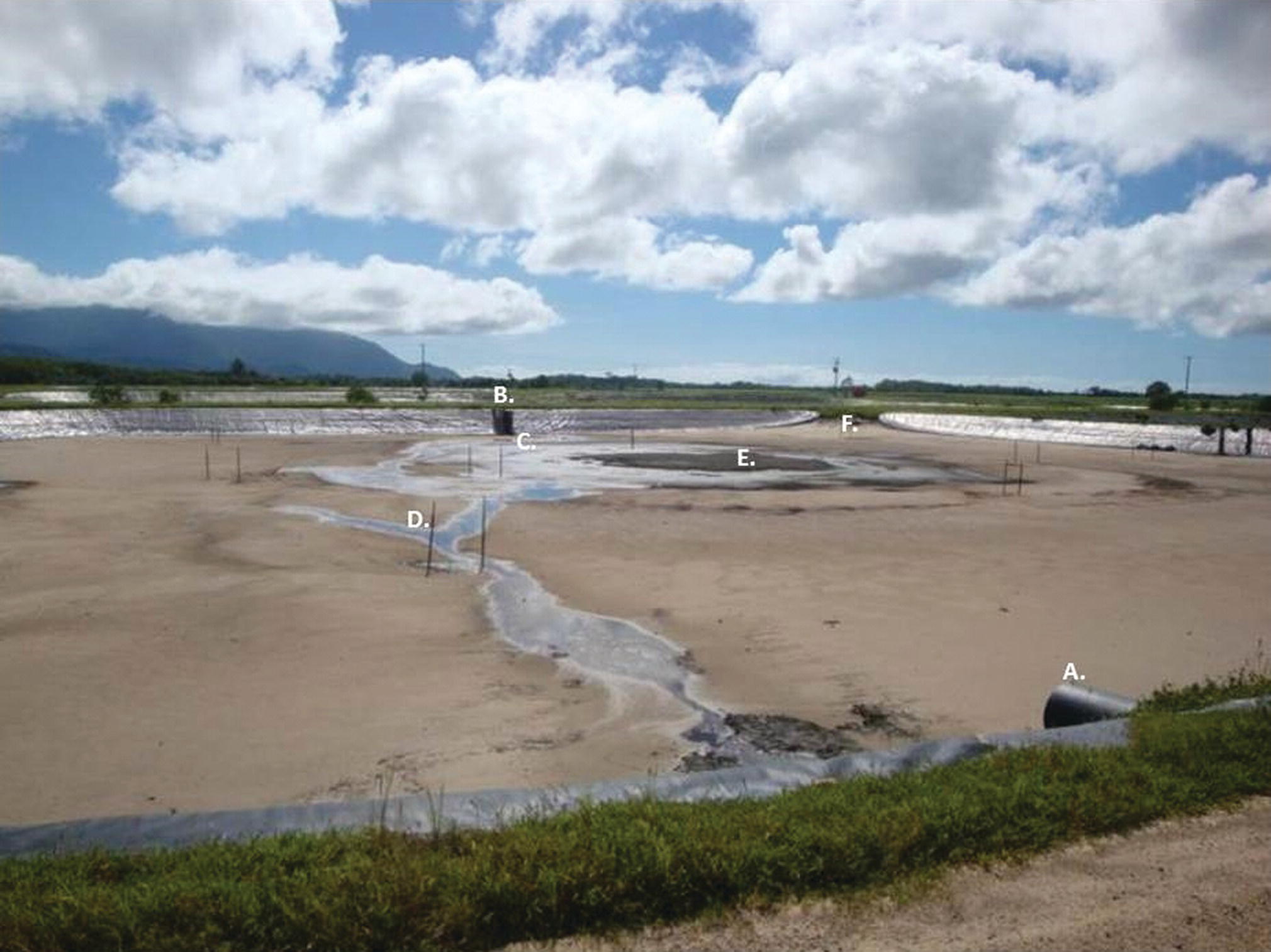
Figure 3.2 Drained shrimp pond showing: (A) Water supply inlet; (B) Drainage outlet monk; (C) Harvest sump; (D) Mooring stakes for aerators; (E) Accumulation of waste from circular water movement directed by aerators; (F) Vehicle access ramp. Note plastic lined walls and earthen substrate.
Source: Reproduced with permission from Igor Pirozzi.
3.3.1.4 Pond Walls
Wall design requires consideration of both wall height and wall slope. Wall height is governed by the depth of the pond, wave height and freeboard. Freeboard is the additional height above normal water and wave height to allow for extreme storm events resulting in raised water levels or greater wave height. Pond depth is generally in the range of 0.8 to 1.8 m. Such depths allow adequate light penetration for primary production and enough depth to reduce temperature fluctuations while decreasing the chance of both oxygen and temperature stratification.
The photosynthetically productive depths of ponds are limited by the penetration of light through the water column and, consequently, ponds are generally shallow compared with their surface area. This is because, unlike smaller culture systems, in which aeration can be used to promote gas exchange, and, unlike systems with continuous water flow, the pond water mass depends on gas exchange at the surface for both oxygen uptake and carbon dioxide removal at night. Gas exchange and diffusion are slow processes and it is possible to have strong stratification of dissolved oxygen through the pond water column. This stratification increases with water depth and is therefore a limiting factor for water depth, despite some aeration systems for pond.
Sunlight penetration can also warm the water, creating higher temperatures at lower pond depths. If a pond is too deep, warming will occur to a certain depth. This may create a thermocline with water below that depth substantially cooler than water above. The creation of thermoclines can result in anoxic, cold‐water layers that can invert and result in substantial stock loses.
Settlement of the wall must also be considered when constructing the pond. Settlement generally varies from 5% to 10%, depending on the soil type used for construction. It is recommended that 10% additional height be allowed to take account of settlement (Yoo and Boyd, 1994).
Wall slope depends on the stability of the soil at the site, the erosion protection and what is deemed as acceptable maintenance. Working with stable soils to achieve minimal erosion, an internal wall slope of between 1:2 (vertical–horizontal) and 1:3 is recommended, and the external wall slope should be between 1:2.5 and 1:3.5. In practice, both slopes are often decreased to ~1:1 (internal) and 1:2 (external) to reduce the capital cost of construction. This also increases maintenance costs. If erosion protection is included, e.g., vegetation above the water line and stone below the water line, slopes can be reduced further. Wall reinforcing can allow the use of vertical walls, although this is more expensive.
Walls must also have a top width to allow appropriate access to the pond. Top widths depend on the height of the wall and the activity to be conducted around the pond. Recommended top widths (Yoo and Boyd, 1994) are related to wall height, but generally do not consider the activity around the pond. Farm machinery is often used around the pond during normal operation, and these vehicles will require a top width greater than that recommended.
3.3.1.5 Pond Floors
The main considerations in pond floor design are pond drainage and harvesting. If a pond is to be drained to collect culture stock, the bottom must be smooth to prevent water collecting in hollows. A bottom gradient of 0.3% to 0.6% is used to effectively drain water to the end of the pond or to a central drain (Wang and Fast, 1992). Additional channels (30–50 cm wide and 10–20 cm deep) may be cut to facilitate drainage. At the lower end of the drainage system there may be a harvest sump, usually about 10–20 cm deep and occupying 0.5–1.0% of the total pond area.
3.3.2 Water Supply (Inlets) and Drainage System (Outlets)
Inlets and outlets are important components of ponds and need to be secure, easy to operate and adequately sized. The exchange of water through a pond is controlled via the inlet. Inlets may be pipes, channels or sluices (an artificial channel for conducting water). Flow through the inlets can be regulated using valves (pipes) or boards (channels and sluices) or by the use of pumps.
In many ponds, water must be filtered to prevent the inclusion of organisms that may be predators, competitors or vectors for disease. To do this, the water is screened using either a simple nylon sock or bag over a pipe or a screen/filter box in the channel or sluice. Socks and screens must be sized appropriately to remove anticipated predators.
Outlets serve a number of functions and are used to:
- adjust and hold the water level;
- drain or partially drain the pond;
- drain water from specific levels of the pond;
- provide an overflow in a continually flowing pond; and
- screen and collect culture stock.
Outlets are usually pipes or weir gates, which are also known as ‘monks’. Pipes are cheap, simple and convenient for small ponds; however, they are not adequate for larger ponds. Weir gates are vertical control boxes attached to waste pipes or channels (Figure 3.3). They are a combination of screens to regulate animal movements, boards to regulate water level and flow, and pipes or channels to move the water from the pond. Landau (1992) and Yoo & Boyd (1994) provide detailed descriptions of pond outlets.
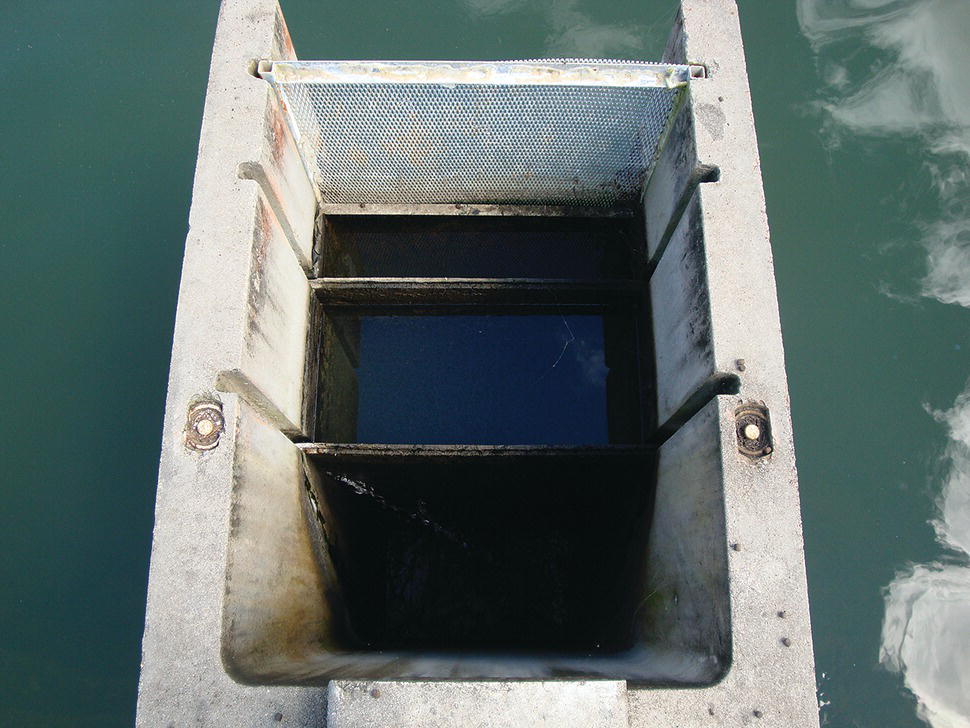
Figure 3.3 A weir gate or ‘monk’ controlling effluent water from a shrimp culture pond. Grooves in the concrete walls hold a screen (top) to regulate animal movements and boards (middle and bottom) regulate water level and flow. Water passes through the screen and over the boards and is drained away from the pond in a channel.
Source: Reproduced with permission from Igor Pirozzi.
3.3.3 Cages
Originally, the cages used for aquaculture consisted of poles or stakes driven into the sediment of shallow lakes or bays with netting stretched around them. These are still in use and are referred to as net pens or hapas. Modern cages are floating structures with a net suspended below. They may be square or rectangular (Figure 3.4), or round (Figure 3.5). Floating cages may be small and of limited strength or they may be many thousands of cubic metres in volume and designed for use in the open ocean (Figure 1.8). Cages are used for fish culture in their grow‐out phase up to their market size.
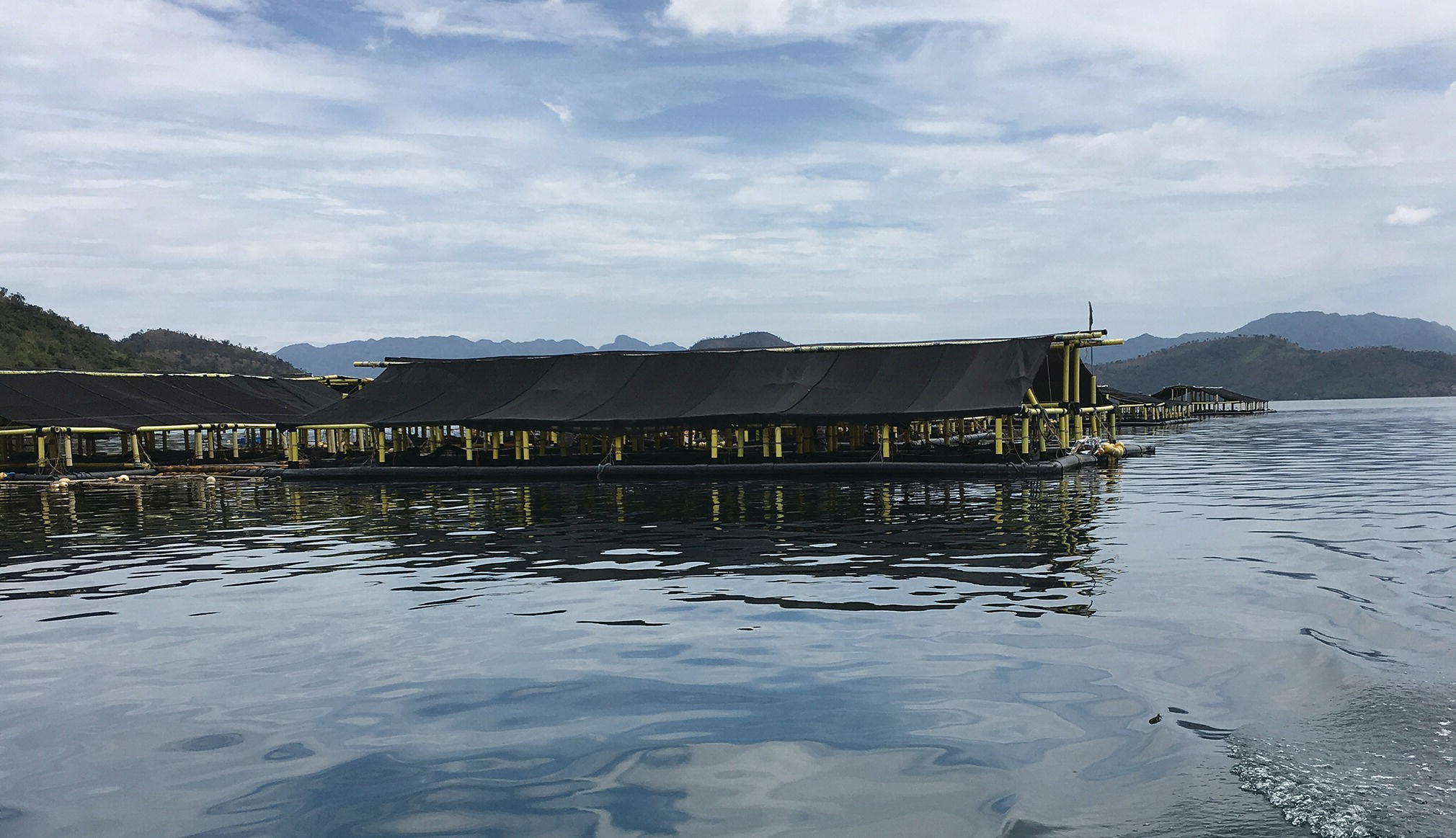
Figure 3.4 Grouper cage farm in the Philippines. Note buoyant HDPE collars.
Source: Reproduced with permission from Igor Pirozzi.
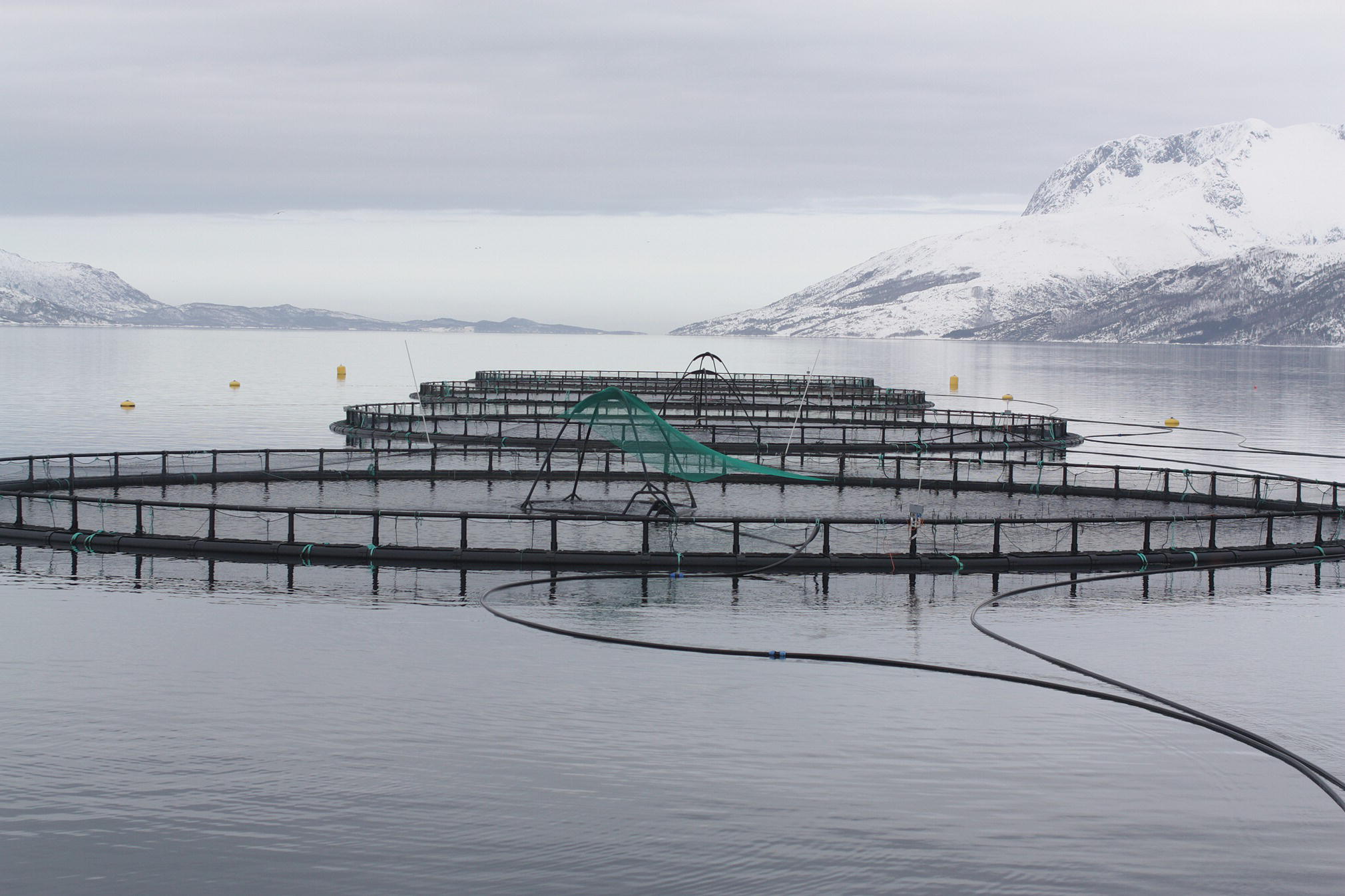
Figure 3.5 Fish cages holding Atlantic salmon (Salmo salar) in Velfjorden, Brønnøy, Norway. The fish are enclosed within underwater nets suspended from the circular floating structures.
Source: Photograph by T. Bjørkan. Reproduced under the terms of the Creative Commons Attribution Share Alike Licence, CC BY‐SA 3.0.
Cages are intermediate to tanks and ponds for capital costs, and are relatively cheap to operate, requiring maintenance but no pumping. Cages located in open systems allow no control over water quality and therefore require a good site with adequate exchange of high‐quality water. If sited correctly, intensive farming at stocking densities up to 15–40 kg/m3 can be achieved. Being situated in ambient water bodies, cages may have problems with:
- fouling of the meshes by seaweeds, bivalves and sponges, which reduce the flow of water through the cage;
- predators, e.g., seals, birds;
- parasites;
- diseases, which are difficult to manage, as cultured stock are difficult to observe and diseases are not easily treated except with medicated feeds; and
- algal blooms.
Cages can be sited in protected inshore ocean locations, such as bays, lochs and fjords or in open seas. Cages may also be used in large freshwater lakes and ponds. Sea cages are generally used in groups, either individually or linked together, and anchored to the substrate. In these groups, they can be serviced, and the fish fed and managed from a base facility on the adjacent shore or from a proximate floating facility.
Cages may be used in combination with ponds, where the cage is used to contain the culture species and the pond is used to manage water quality. This technology has now progressed to the use of ‘floating raceways’ where the cultured species is maintained in a raceway floating within a larger water body that provides for water quality management. These types of systems are being used in ‘irrigation’ districts where water previously stored in large reservoirs solely to irrigate crops now has multiple uses through fish culture. This has resulted in increased water use efficiency per unit of water by utilising horticultural and aquaculture production.
The design of cages varies depending upon their use and location.
- Ponds. These cages are small, (approximately 4–6 m and 1.5 m deep) and are secured to stakes driven into the bottom of shallow ponds. The cages are located within a very ‘friendly’ environment and are accessed easily from the pond wall or a floating walkway.
- Lakes, estuaries or protected bays. These cages tend to be much larger (10–40 m diameter) and are secured to the bottom of the waterway by anchoring lines. The forces associated with these environments are greater than those found in ponds as a result of tidal currents, wind‐generated waves (<1 m) and swells. Again, these cages are easily accessed from shore or by a short trip in a small powerboat.
- Open seas. These cages must undergo the rigours of oceanic swells and wind‐driven waves in excess of 4 m (Figure 3.5). The cages are very large, and may be 50 m or more in diameter. Often located far offshore, these cages require attached working areas.
3.3.3.1 Cage Features
Irrespective of the use of the cage, there are structures that are common features. The aims of these structures are to hold and protect culture stock, and to maintain the position, size and shape of the cage.
- Float. The float keeps the cage at the surface of the water and helps maintain the shape of the cage in both vertical and horizontal planes. Floats may be large‐diameter rubber hose or high‐density polyethylene tubes/pipes.
- Collar. The collar maintains the shape of the cage in the horizontal plane. It may simply be a ring of metal placed at the bottom of the cage to weigh the cage down in the required shape or it can be a complicated design involving flotation and weights.
- Nets. There are several types of nets for cages.
- Main net. This net holds the cultured stock. It must resist ripping by objects and predators, and be able to hold the biomass when nets are lifted for harvest. The mesh must be designed to prevent cultured fish being caught in the netting. Besides holding the fish, this net must also permit adequate water flow through the cages to maintain water quality.
- Predator net. This net keeps sea‐borne predators away from the cultured stock to reduce predation. It is placed outside the main net.
- Covering net. This net is placed over the top of the cages to prevent birds landing, fouling, scavenging and preying on cultured stock.
- Jump net. This net projects vertically out of the water around the main net, preventing fish escaping.
- Moorings. These are used to secure the cage at the selected site. Moorings are often specific to the type of cage and for larger cages are generally specified by the manufacturers.
Further details on cages and cage culture are provided by Beveridge (2004) and comprehensive information on the design, installation, operation and management of high‐density polyethylene (HDPE) cages in modern industrial marine aquaculture is provided by Cardia and Lovatelli (2015).
3.3.4 Pens
Pens, enclosures or hapas are used in shallow water, typically in ponds, to create a restricted environment for culture of fish and some crustaceans. They are not usually large, being in the order of tens of square metres or less. The walls of the enclosures may be closely spaced stakes, such as bamboo stems or mangrove branches, or wire and other mesh (Figure 3.6). This system of culture is practised mainly in developing countries. One interesting exception to the shallow water pen is the use of mesh fences or walls to enclose bottom‐dwelling scallops. These pens are of sufficient height to prevent the scallops from swimming over the wall. They may use floats to allow the mesh to rise and fall with the tide (Quayle and Newkirk, 1989). Similar enclosures may also be used for culture of gastropod molluscs.
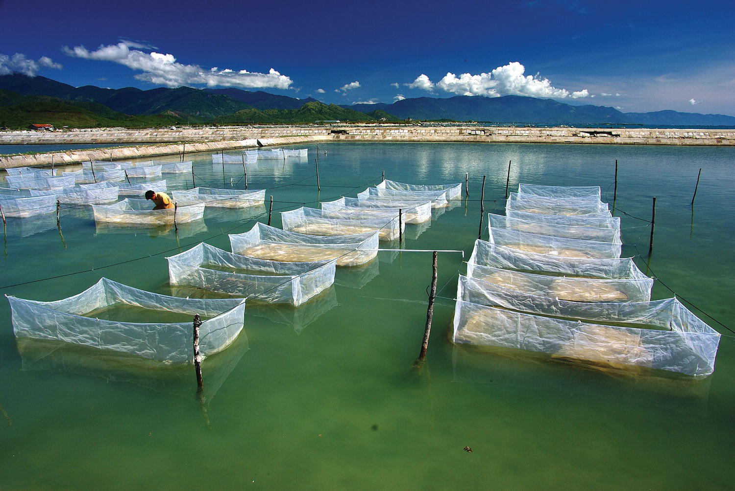
Figure 3.6 Hapa nets within a large concrete and block walled pond at the Research Institute for Aquaculture (RIA3), Central National Marine Breeding Center, Van Ninh district, Khanh Hoa province, Vietnam. The hapas are used for culture of juvenile sea cucumbers (Holothuria scabra).
Source: Photograph by Dr D. Mills. Reproduced with permission from WorldFish.
3.3.5 Substrates, Racks and Suspended Culture
Surfaces are used, as would be expected, for culture of bottom‐dwelling and attached species. This category is taken to apply to species that are grown in the field for most of their culture, rather than in tanks with artificial surfaces, e.g., abalone culture that occurs totally in tanks.
The techniques used in this category are quite varied, reflecting the diverse range of organisms that are cultured and their varying environmental requirements.
Some bivalves attach permanently to hard substrates. Their larvae settle and metamorphose on attractive substrates, which are put out in the field at appropriate sites and times to obtain juveniles. The juveniles may then be grown on the original substrate or are removed to another culture system. The secondary culture systems may be:
- mesh trays on horizontal racks above the substrate in the intertidal zone (Figure 5.2)
- suspension in/on various kinds of nets, ropes, trays and baskets, hanging down at intervals from a horizontal long‐line or raft on the surface (Figure 3.7; Figure 2.14)
Figure 3.7 An extensive raft system in Khánh Hòa Province, Vietnam, used for the culture of oysters and other bivalve molluscs which are held in baskets suspended from the rafts. Larger nets are also strung between sections of the raft and used for small‐scale fish culture.
Source: Reproduced with permission from Paul Southgate.
More on these techniques and their application to bivalve mollusc culture can be found in Chapter 24.
Other benthic organisms, e.g., seaweeds and sponges, may be grown tied to lines stretched above the substrate.
3.3.6 Tanks and Raceways
Tanks are second to ponds as the most commonly used structures for aquaculture. Tanks are generally situated above ground on a solid base and may be used indoors or outdoors. Tanks have the advantage of allowing the use of land normally unsuitable for aquaculture, as the water is contained within the structures without contact with the surrounding soils. There is a wide range of dimensions and sizes of tanks, corresponding to their wide range of uses in culturing microalgae, macroalgae, and various life cycle stages of fish and invertebrates (Figure 3.8; Figure 3.9). They range in size from tens of litres to hundreds of cubic metres.
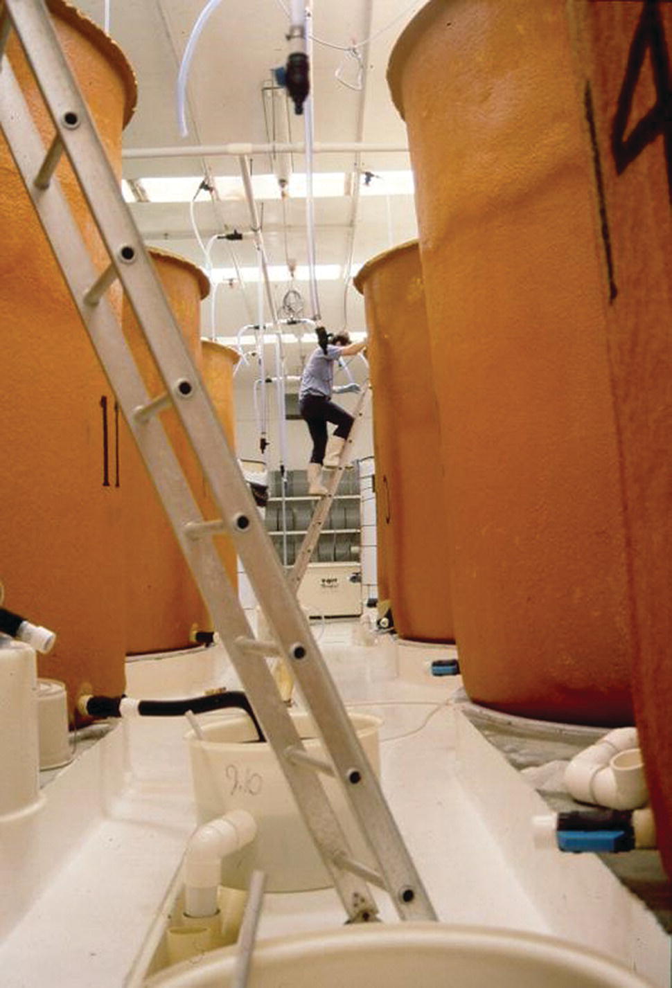
Figure 3.8 Large (20 000 L) fiberglass hatchery culture tanks at an oyster hatchery in Tasmania, Australia. Note that access to the top of the tanks requires a ladder, and overhead delivery of water, air and microalgae.
Source: Reproduced with permission from Paul Southgate.

Figure 3.9 Large concrete larval culture tanks at the Research Institute for Aquaculture (RIA3), Central National Marine Breeding Center, Van Ninh district, Khanh Hoa province, Vietnam. The tanks are used for sea cucumbers, shrimp and gastropod culture.
Source: Reproduced with permission from Paul Southgate.
Raceways are basically elongated tanks in which water enters at one end and exits at the other. They generally consist of elongate, narrow and shallow systems with continuous water flow. The limited cross‐section of the raceway together with the strong flow rate are designed to maintain continuous unidirectional flow along the raceway. It is a particularly suitable system for some fish, such as salmonids, that live in shallow streams and swim against the current (Figure 3.10). Raceways generally require large amounts of water per unit volume of the system. Freshwater raceways, the most common form, need to be sited near a freshwater spring or a substantial stream that does not dry up. As with other aquaculture, they need an unpolluted source of water. A potential problem with raceways is the deterioration of water quality along their length.
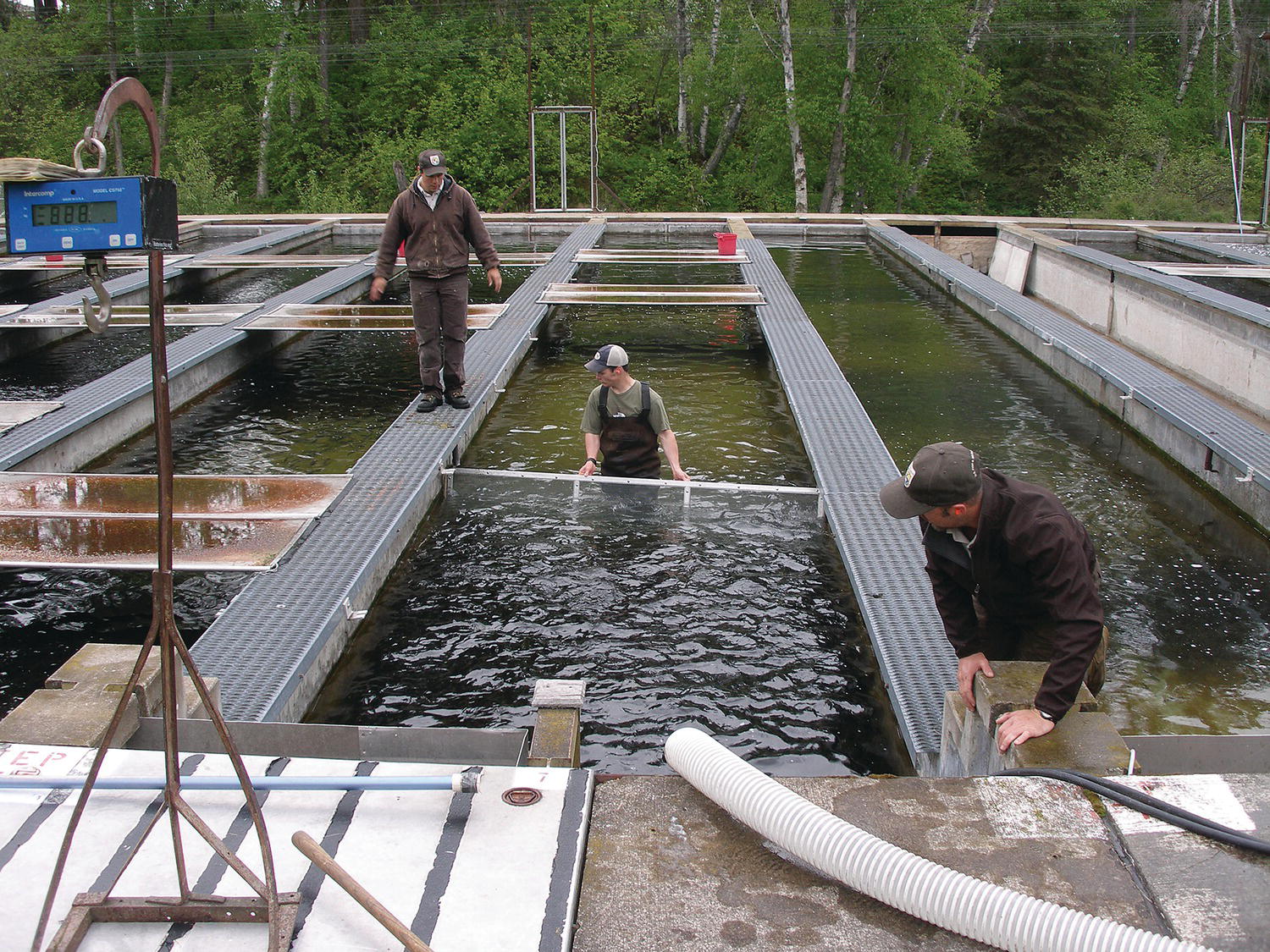
Figure 3.10 Creston National Fish Hatchery staff guide rainbow trout (Oncorhynchus mykiss) to one end of a concrete raceway.
Source: Reproduced with permission from U.S. Fish and Wildlife Service.
Tanks are most commonly used for culturing the early developmental stages of fish, bivalves and crustaceans, and for culturing high‐value fish species. Raceways are also used for culturing high‐value fish. As with ponds, there are a variety of tank systems ranging from flow‐through systems, in which the tank system is simply a confinement for the animals, to recirculating tank systems (section 2.5.4), in which the water is used, treated and re‐used while maintaining a high density of animals. The majority of raceways are flow‐through.
3.3.6.1 Structure
Tanks and raceways are most commonly constructed from concrete or synthetics, such as fibreglass. The major considerations in material selection are:
- strength;
- abrasiveness to the animals;
- cost;
- possible chemical residues; and
- shape.
The shape must allow good water flow to maintain uniform water quality and prevent build‐up of wastes in ‘dead spots’. The shape of tanks varies greatly from hemispherical to flat‐bottom and square. Circulation and self‐cleaning ability of tanks is a function of shape, depth and water exchange. Tanks that are circular in the horizontal plane with conical bottoms are generally considered to provide the best circulation and self‐cleaning properties, for the lowest flow or exchange rates. The flow of water in raceways, being linear from inlet to outlet, facilitates cleaning and more uniform water quality. In abalone culture, flat bottomed, rectangular shallow tanks are combined with high exchange rates.
3.3.6.2 Inlets and Outlets
As discussed for ponds, the major function of the inlet for tanks and raceways is to regulate water exchange. Generally, water flow into tanks is regulated using a valve, whereas flow to raceways may be regulated by either valves or sluices.
Inlets in tanks or raceways, however, must also provide water movement. The delivery of water into the tank or raceway must be such that it facilitates an even movement of water throughout the structure, maintaining uniform water quality. In raceways this is often achieved by delivering water at multiple points along the input end of the raceway either through perforated pipes or over spillways. Maintaining uniform water quality may also be assisted by having multiple inlets along the length of the raceway.
Water in tanks is generally supplied through pipes and the number of input points, combined with directional inlet(s), will govern water movement and assist with aeration in some systems.
The functions of outlets from tanks and raceways include:
- maintaining water level;
- retaining cultured animals;
- allowing drainage of the structure; and
- removal of wastes.
Outlets for tanks usually consist of a vertical or horizontal pipe, a screen to retain stock (or a collection trap for stock) and pipes to direct water either back to a sump or to waste. However, given the diversity of tank systems and the flow design for these systems, there are many outlet designs.
3.3.7 Recirculating System Design
Recirculating systems have minimal connection with the ambient environment and the original water source and there is minimal exchange of water during a production cycle (section 2.5.4). Feed input, animal metabolism, uneaten feed and faeces production all impact upon water quality. As a result, special consideration must be given to the design of recirculating aquaculture systems with regard to removal of waste products and maintenance of appropriate water quality. The various means of waste processing and some typical components used in recirculating systems are shown in Figure 3.11. Parameters that require regulating in an intensive recirculating tank system are:
- particulate matter (settleable, suspended and fine waste solids) in the system resulting from feed and faeces;
- nitrogenous wastes (unionised ammonia, ionised ammonia, nitrite and nitrate, which are often expressed as NH3‐N, NH4‐N, NO2‐N and NO3‐N respectively);
- dissolved gases (O2, CO2 and N2);
- pathogens;
- pH; and
- alkalinity.
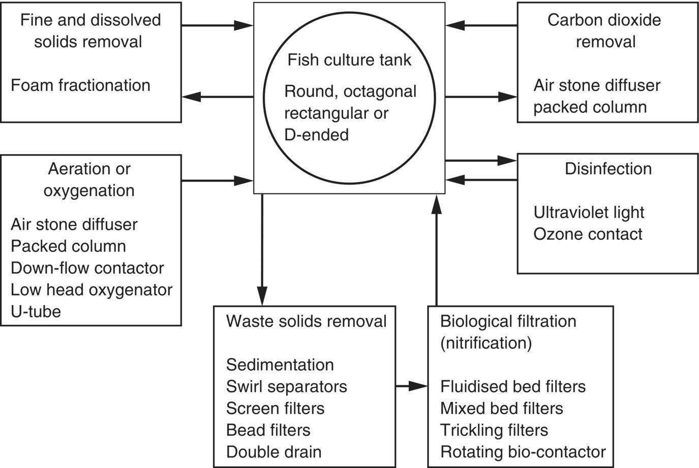
Figure 3.11 The water treatment processes and typical components of a major recirculating system for intensive culture of fish.
Source: Reproduced from Losordo et al. (2001) with permission of the World Aquaculture Society.
For more detail on each of these aspects of water quality refer to Chapter 4.
In recirculating tank systems, water quality is maintained by pumping the culture water through specialised filtration and aeration equipment. The components of intensive recirculating tank systems are described below and further descriptions of the various components of these systems are provided by Losordo et al. (2001).
Waste including uneaten feed, faeces and fish metabolites that are produced in intensive aquaculture systems must be dealt with well before the breakdown products, such as ammonia, can accumulate to toxic levels (see Chapter 4). There are many strategies for dealing with waste products in aquaculture systems which include implementing good feed management practices, undertaking water exchanges as well as utilizing appropriate equipment to treat waste water. Of the latter, the types of equipment used will generally depend on the particle size of the waste product that is to be treated. The size of waste particulates can be classed nominally as settleable (≥10 µm), suspended (≥1 µm), colloidal (<1 µm – 10−3 µm) and dissolved (<10−3 µm).
3.3.7.1 Solids Filtration
The method used for removal of solid wastes depends on the type of waste. Settleable solids sink and may be removed by gravity and flow, on a continuous basis, or by siphoning on a regular basis. Alternatively, settleable solids can be maintained in suspension with continuous agitation from aeration, water flow and stock movement, and removed using a mesh screen or allowed to flow into settlement basins or tanks. Settleable solids can also be removed by centrifugal force using a swirl separator or hydrocyclone.
Suspended solids that will not settle out by gravity are generally removed from recirculating tank systems using mechanical filtration.
- Screen filters are made of a fine mesh through which water flows and the suspended solids are retained on the screen. The screen filters are then periodically or continuously cleaned. Types of self‐cleaning screen filters include rotating screen filters and rotating drum filters.
- Particulate filters, include sand filters and expandable granular media filters. Particulate filters also require cleaning, a process known as ‘backwashing’.
- Foam fractionators (or protein skimmers) are used to remove very fine suspended solids and dissolved organic compounds (DOCs) that cannot be removed by mechanical filtration in recirculation systems. Air is injected into the bottom of the vertical fractionator column, usually through a venturi system, forming fine bubbles which rise up to create a foam at the surface. This waste foam is then collected and removed. Foam fractionation works through the physical adsorption (bonding) of the DOCs to fine bubbles as they rise through the fractionator column. The efficiency of the removal of DOCs and fine suspended solids depends on the size of the air bubbles (the smaller the better) and contact time (the longer the better). Increased contact time is usually achieved with a counter‐current design.
3.3.7.2 Ammonia‐N and Nitrite‐N Removal
Toxic levels of ammonia and nitrite can quickly build up particularly in intensive closed aquaculture systems. There is an equilibrium between the concentration of toxic ammonia (NH3) and the less toxic ammonium ions (NH4+) in solution:
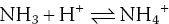
The sum of ammonia and ammonium is the Total Ammonia Nitrogen (TAN) and because these are in equilibrium, reducing one compound will also reduce the other. This equilibrium, and therefore ammonia toxicity, is pH and temperature dependent with relative levels of ammonia toxicity increasing as these variables also increase (section 4.3). Reducing pH and temperature to the lowest possible acceptable levels for the cultured animals will therefore help alleviate problems associated with high ammonia accumulation in closed systems, but this of course cannot be considered the only solution to accumulation of toxic nitrogenous compounds.
In aquaculture, ammonia and nitrite (also toxic to fish) can be effectively removed through nitrification in biofiltration systems. This process involves the bacterial breakdown of:
- NH4+ to nitrite (NO2−)
- NO2− to nitrate (NO3−)
Steps 1 and 2 (nitrification) occur simultaneously under aerobic conditions with nitrate the end product. Generally, fish have a high tolerance to nitrate therefore further anaerobic denitrification, Step 3, is not normally considered as critical if there is some exchange of water in the system.
- NO3− to nitrogen gas (N2)
The concentration at which nitrate is toxic to marine fish can vary greatly depending on the species. For example nitrate levels >500 mg NO3− /L are toxic for the planehead filefish, while nitrate toxicity doesn’t occur until levels are >3000 mg NO3− /L for beaugregory (Pierce et al., 1993). Further detail on TAN are reviewed in section 4.3.7.
There are numerous technologies available for removing TAN from water, including air stripping, ion exchange, biological filtration and removal by algae. Biological filtration is the most widely used method. Biological filters are available in a variety of forms including trickle filters, submerged filters, rotating biological contactors, packed tower filters and fluidised bed filters.
Biofilters promote the aerobic conversion (nitrification) of TAN (NH3/NH4+) to nitrite (NO2−) and nitrate NO3− through the provision of biomedia with a large surface area to volume ratio on which nitrifying bacteria can grow. Regardless of the type of biofilter, the efficiency of the nitrification system will depend on the specific surface area (SSA) of the bio‐media and the contact time of waste water, with stock biomass and feed (dietary protein) input determining the size of the biofiltration unit that is required.
3.3.7.3 Dissolved Oxygen
Aeration is the dissolving of oxygen from the atmosphere into water. It is an important aspect of the design of recirculating tank systems, as it is necessary to maintain dissolved oxygen at the required level for the cultured animals. It is also important to maintain dissolved carbon dioxide below 20 mg/L to maintain favourable pH, reduce stress and maximise growth. There are several types of aeration devices commonly used in recirculating tank systems, including diffuser aerators, mechanical aerators such as paddle wheels (Figure 3.12), vertical pump aerators and packed column aerators.
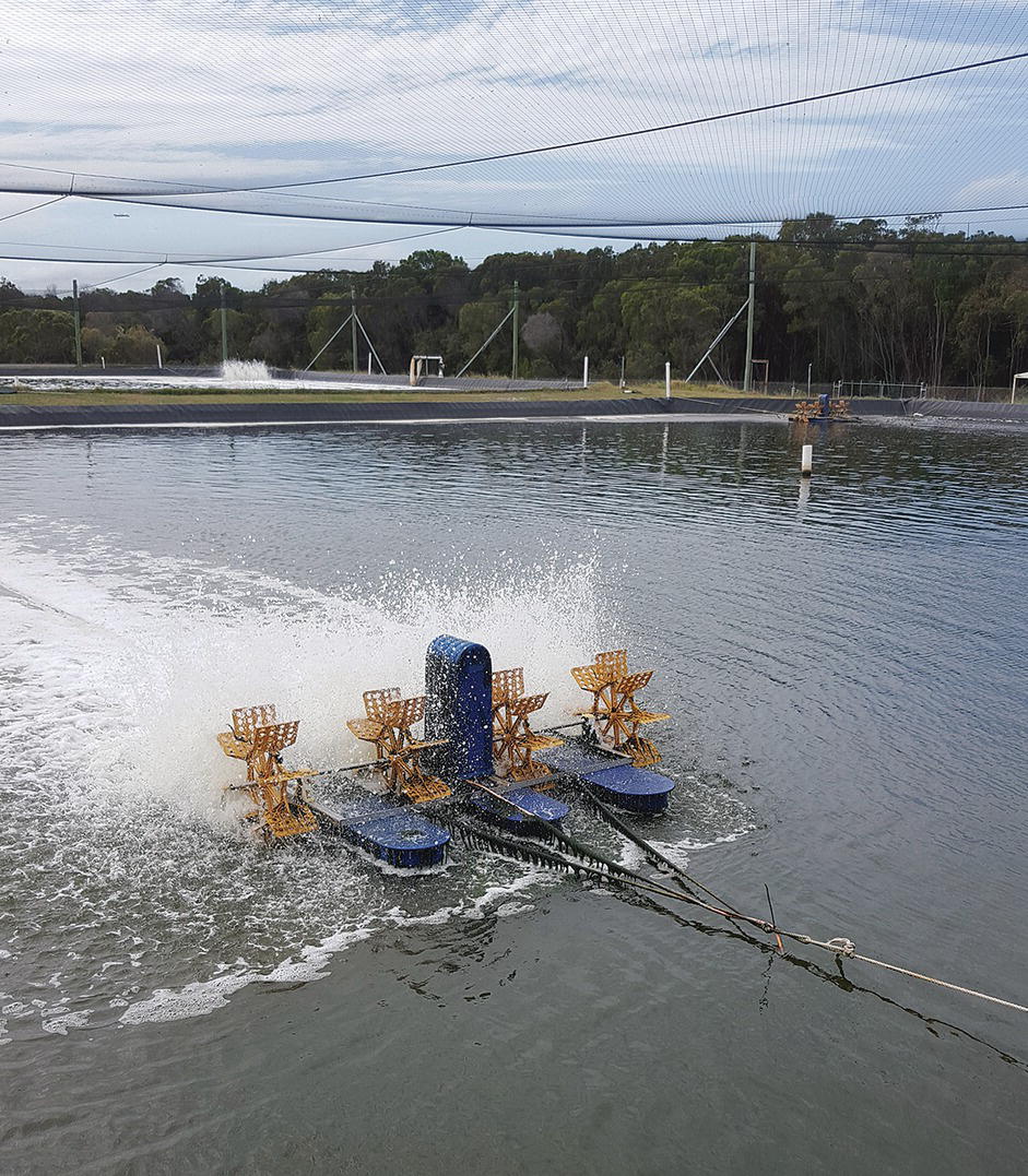
Figure 3.12 Paddlewheel aerators are an effective way of maintaining good dissolved oxygen levels in pond aquaculture. Note that this is a plastic‐lined pond built on a porous substrate (sand) with overhead netting to protect from predators. Other examples of pond aerators are shown in Figs. 4.9 and 4.10.
Source: Reproduced with permission from Paul Southgate.
Oxygenation is the process of pure oxygen transfer to water and is used when oxygen consumption is greater than the capacity to transfer oxygen through aeration using air (which is only 21% oxygen). Oxygen can be supplied as compressed oxygen gas and liquid oxygen from commercial sources or it can be produced on‐site by oxygen generators. The choice is generally one of cost and reliability of electricity supply to produce oxygen on site. As the transfer of gas to water using diffusers is poor (less than 40% for oxygen), specialised components to deliver oxygen to recirculating tank systems have been developed. These components can effectively transfer greater than 90% of oxygen to the water. A variety of oxygenation devices are available.
3.3.7.4 Pathogens
Continuous disinfection of water in a recirculating tank system can help to limit the introduction and spread of disease, and the build‐up of pathogenic bacteria, e.g., Vibrio species, to levels at which they cause mortality in the stock. Ultraviolet (UV) irradiation and ozonation are two methods of continuous disinfection used in recirculating tank systems.
This section has dealt primarily with recirculating tank systems used for intensive culture, but larger‐scale recirculation systems are now being developed for pond culture. In ponds with intensive culture, e.g., shrimp culture, it is difficult to operate without regular water exchange. However, pond systems in which there is very limited or no water exchange throughout a growing season are now being developed.
3.4 Plumbing and Pumps
The following section falls within the scope of aquaculture system engineering. Further detailed information on aspects of aquaculture engineering and fluid mechanics may be obtained from an appropriate text, for example, Wheaton (1977) is still regarded as the classic text in this field and more recently, Lekang (2013a) provides comprehensive information on this topic.
3.4.1 Pipes
3.4.1.1 General
Pipes, channels and pumps are basic components of most aquaculture systems, except those that are open and static (section 2.5). Water can be conducted around an aquaculture facility using either pipes or open channels. The advantages of pipes include the ability to pump water at pressure and up a pressure gradient. The disadvantages of pipes compared with open channels include larger construction costs per unit water flow, larger frictional losses causing higher pumping costs and lower achievable rates of water flow. However, channels cannot deliver water at pressure or up a pressure gradient. As such, pipes are more commonly used for the delivery of water, except when very large flow rates are required, and channels are employed largely as drains. Often a combination of pipes and channels are used where large pipes are used to ‘lift’ the water a short distance up the pressure gradient and into distribution channels (Figure 22.6). This provides the advantage of pumping from estuaries, rivers and oceans onto farm, and avoids the costs associated with lengthy piping systems.
The aim of pipe selection is to obtain the optimum size of pipe (usually expressed as internal diameter in mm), the correct pipe material, and the best pressure ratings to meet the pumping pressure and the flow capacities required for the facility.
When selecting pipes for a given flow there is a choice between
- smaller pipes with higher flow velocity and pressure and
- larger pipes with lower flow velocity and pressure.
The advantage of using smaller pipes is that the capital cost of construction is much reduced, with the cost of pipes increasing rapidly with pipe diameter and pressure rating. The disadvantages of using smaller pipes are that they require greater water velocities for a given water volume and produce higher frictional forces and pumping costs. Higher frictional forces also result in larger pressure heads to be pumped against, increasing the strength (or class) of pipe required and, to an extent, increasing the capital cost of construction. Selection of smaller‐diameter pipes during initial construction also greatly reduces the ability to expand the capabilities of the system in the future.
In addition, the higher the flow rate the greater the possibility of water‐hammer1 occurring. As a rule, it is better to have the water velocity as low as possible within the constraints of the capital costs of construction.
If the flow rate and flow/water velocity required are known, then the required pipe can be determined. Manufacturers of thermoplastic piping can provide charts, known as nomograms, to facilitate the correct choice of pipe by cross‐referencing flow rate and water velocity. Pipes, however, are manufactured in discrete sizes and pressure‐class ratings (i.e., the maximum pressure a pipe can work under), not all of which are readily available or provide the same selection of fittings. In general, the velocity criteria will not provide a clear decision on the best pipe to use and will result in a choice of two sizes. The wise decision is to be conservative and select the larger pipe.
Another conservative measure in system design is to duplicate pumps, major plumbing and other components of the system. Even in the best‐maintained systems there may be abrupt equipment failures. Duplication allows the problem component to be by‐passed without having to shut the system down while repairs or replacements are affected. Furthermore, there are a number of routine maintenance activities that can be conducted without otherwise having to shut the whole system down. Some of these activities are:
- servicing pumps and other components in the system;
- back‐flushing filters to remove sediment or otherwise renewing filter surfaces;
- clearing intake pipes of bio‐fouling; and
- flushing general plumbing to clear out accumulated sediment.
3.4.1.2 Frictional Losses
Frictional losses are due to factors such as flow type, flow rate or velocity, pipe length and the roughness of the internal surface of the pipe. In aquaculture systems, flow is turbulent, creating internal eddies that collide with the side of the pipe, causing increased internal friction resulting in increased energy losses. Flow rate depends on the water requirements of the facility, while flow velocity results from the required flow and the pipe diameter. Pipe length is a result of facility layout and design. Roughness of the internal surface of the pipe is due to sand scour factors, scale formation, sediment deposit and bio‐fouling. Frictional losses will also vary with salinity and temperature, but these changes are only slight.
Frictional losses are generally measured in head (elevation units, m) or pressure difference. Frictional losses for pipes are available in nomograms and flow charts from the manufacturer for standard conditions. Yoo and Boyd (1994) and Lekang (2013a) provide further information on how each of the above factors affects friction and, therefore, how decisions on pipe size and flow rates may affect the operating of the system.
3.4.1.3 Fittings
Plumbing fittings are the pieces that:
- join pipes or in‐line components to the line;
- redirect and split the flow; and
- change the pipe diameter.
All these fittings provide resistance to the flow and must be allowed for in the calculation of friction within the system.
Losses due to fittings depend on:
- type of fittings or transition (e.g., bends, couplings);
- abruptness of flow change;
- materials and condition of inner surface; and
- velocity of water movement.
In addition to fittings, there may be dramatic head losses from in‐line components (e.g., UV sterilisers and sand filters). These effects on flow rate are given by the manufacturers and are described by Yoo and Boyd (1994) and Lekang (2013a).
3.4.1.4 Choice of Plumbing Materials
For the majority of applications, and in particular for delivery of water over extended distances with pipe diameter of less than 200 mm, the choice of plumbing materials comes down to two types of general‐purpose, cost‐effective thermoplastics: rigid PVC (polyvinyl chloride) and high‐density polyethylene (HDPE). For special applications, e.g., in outdoor areas exposed to high UV levels, high temperature (>50 °C) or high abrasion due to water‐borne sand, and in high‐impact areas, especially adjacent to large pumps, acrylonitrile butadiene styrene (ABS) pipe can be used although this material can be more expensive. When the internal diameter exceeds 200 mm, and especially in high‐impact areas, concrete and steel tend to be used as these are more durable and cost‐effective.
3.4.2 Two Common Problems in Plumbing Design
Two of the more common problems in plumbing design are water hammer and bio‐fouling.
Water hammer is caused by rapid stopping or changing in direction of flow (Lekang, 2013a) that creates a wave of backpressure, resulting in a loud bang, hence water ‘hammer’. It is the noise that may be heard in domestic plumbing when taps are turned on. The pressure wave is added to the existing pressure in the system and has the ability to rupture plumping or permanently damage piping, pumps and in‐line equipment. The magnitude of the pressure wave is related to the velocity of water in the pipe, pipe length and rate of change of flow.
The risk of water hammer increases with:
- water velocity;
- the length of uninterrupted pipe; and
- the abruptness of flow change.
As a result, it is recommended that water velocity in pipes be kept below 1.2 m/s. It is also important to be aware of high‐risk areas in plumbing design. These include design parameters creating flow change at the end of a long length of uninterrupted pipe.
In aquaculture systems, water hammer often originates from rapid opening of a line resulting in a high‐velocity flowing down the pipe. This water eventually encounters a 90° bend or, perhaps, a mostly closed valve, resulting in a sudden change in flow and water hammer. Rapid opening of a line can result from either turning on a valve too quickly or having a pump switch on. In these circumstances it is important to turn valves on slowly. Similarly, the use of ‘soft‐start’ pumps reduces the risk of water hammer from pumps starting. The risk of water hammer can also be mitigated by ensuring that the receiving pipe is full of water, so reducing the resultant flow from the pump, or ensuring that there are no sharp bends or closed valves in the path of the flow. As with opening a valve too quickly, closing a valve in a flowing line too quickly will enhance the risk of water hammer. This is easily corrected by identifying and marking critical valves or using valves that require several turns to shut them, e.g., gate valves, thus extending the time of closing.
The adverse impact of bio‐fouling organisms, algae, sponges, barnacles and other shelled animals has been indicated for cages. Bio‐fouling also occurs on the inner surfaces of aquaculture plumbing. It is a major factor influencing performance in seawater systems, but has a lesser effect on freshwater systems. Bio‐fouling roughens surfaces and thereby increases the friction on the inner surfaces of pipes and fittings. It also blocks protective grills and pipe cavities. Considerable effort is required to reduce bio‐fouling in seawater systems, and it can only be controlled by regular maintenance. It is important during maintenance to remove both the fouling organisms and their calcareous shells, if present. Many methods, e.g., flushing with freshwater and hot water, and anoxia (by having stagnant water in the plumbing for a considerable period), simply kill the organism but do not remove the shells. The most common and effective method of controlling bio‐fouling is to remove the fouling organisms by forcing a rigid structure through the pipe under pressure. These devices are known as ‘pigs’ or ‘snakes’, and access for pigs or snakes into and out of the system must be taken into account during system design, e.g., by having T‐junctions instead of 90° elbows. Under pressure, the pigs or snakes scrape the internal surface of the pipe, removing both organisms and exoskeletons. Antifouling paints which are commonly used in in marine industries may not be suitable for aquaculture application as they can contain heavy metals and organic biocides. Biofouling especially in marine environments still represents a considerable challenge to the aquaculture industry. Fitridge et al. (2012) recommended six criteria for antifouling strategies: (1) be effective against a broad range of fouling taxa; (2) be environmentally benign; (3) have no negative effects on the cultured species; (4) leave no residues in the cultured species; (5) be able to withstand on‐shore handling and cleaning; and (6) be economically viable.
3.4.3 Open Channel Design
When high water flows are required either into or out of a system, and there is no need to have a pressurised flow, as water can flow by gravity, it is cost effective to replace pipes with open channels. The advantages of open channels compared to closed pipes have already been considered, but there is a further advantage of the high flow capability allowing them to handle high transient flows (i.e., burst pipes and emergency draining of tanks or ponds). There are also the advantages of ease of access for routine cleaning and disinfection, and potential to be used as a harvest sump.
Drains are generally rectangular, semicircular or U‐shaped. They are generally earthen or concrete. Concrete is often used in earthen channels to protect areas vulnerable to erosion, such as the portion of the channel immediately after the delivery pump. Concrete channels are also used for tank systems, both indoors and outdoors. The volume of water that can be moved by a channel is related to the size, shape, construction material and slope of the channel. Further information on how each of the above factors affects the maximum flow for a channel design may be obtained from Yoo and Boyd (1994).
3.4.4 Pumps
An important aspect of aquaculture systems is the correct choice of pump. Although this task is best performed by qualified personnel, it is important to know the types of pumps available and understand factors affecting pump selection. Pumps and pumping are covered in detail by Yoo and Boyd (1994) and Lekang (2013a).
The variety of pumps used in aquaculture can generally be classified into two groups:
- mechanically driven (positive displacement and rotodynamic pumps); and
- air driven (airlift and air/water ballast pumps).
The majority of pumps used for water delivery in aquaculture systems are rotodynamic pumps. They work by continuously imparting energy to the water using a rotating impeller, propeller or rotor. There are three types of rotodynamic pumps.
3.4.4.1 Centrifugal (Radial Flow) Pumps
Water enters the impeller axially (along the axis of rotation) and exits radially in centrifugal pumps. The pressure is due to the centrifugal force of the impeller on the water and the water being contained by the casing of the pump. Centrifugal pumps have a high‐lift/low‐volume characteristic, being able to pump against heads > 15 m. They also have the best suction lift characteristics; however, they perform best if located as near to the water source as possible. Although centrifugal pumps will draw water, they will do so only if they are primed, that is if the line on the suction side and the pump is full of water.
3.4.4.2 Axial Flow Pumps
In axial flow pumps, water enters and leaves along the shaft axis (axially). The pressure is produced by the action of propeller blades (vanes) directly on the water. Axial flow pumps are used for low pressure head, generally < 7 m, and high volume rate, > 1 m3/s. A limitation of these pumps is that they will not draw water, so the propeller must always be submerged.
3.4.4.3 Mixed Flow Pumps
In mixed flow pumps, water enters axially and discharges axially and radially. The pressure developed is due to a combination of centrifugal force and lift due to propellers. These pumps are suitable for medium pressure head, 5–15 m, and flow rate applications.
3.4.4.4 Pump Components
Pumps are an indispensable part of an aquaculture system and understanding their structure and maintenance is important for aquaculturists. There are two main elements to a rotodynamic pump. These are the rotatory element (impeller or propeller on the shaft) and the stationary elements (casing, stuffing box and shaft bearings).
Centrifugal pumps (Figure 3.13) have the following components:
- Casing. The casing converts water velocity leaving the impeller into pressure head. There are two types of casings used in centrifugal pumps. Volute casings spiral out from the centre, increasing casing volume with the spiral, resulting in a decrease in the velocity of water flow and the creation of pressure. Diffuser casings direct water through a set of diffuser vanes. The diffuser allows the conversion into pressure of a greater amount of energy imparted on the water, resulting in higher efficiency.
- Shaft and bearings. The shaft transmits torque of the motor to the impeller. The shaft is supported by bearings to centre the shaft and impeller both radially and axially and to allow for the rotation of the shaft. Bearings may be either sealed or water lubricated.
- Mechanical seals (or stuffing box). The mechanical seals prevent water from leaking around the shaft, which can result in deterioration of the bearings, shaft and motor. Seals are usually rings cut in soft plastic and fitted tightly around the shaft and shaft sleeve. Seals are cheap and readily replaced. Spare seals for crucial pumps are essential to have in stock.
- Impellers. There are three types of impellers and the impeller best suited to the pump is generally governed by the requirements of water to be pumped. Open impellers have vanes that are attached to a central hub and supported by ribs. A small area of faceplate results in large clearances, which allow water‐borne solids to be pumped. However, open impellers are not very efficient because they allow slippage of the impeller through the water. Semi‐closed impellers have a complete faceplate to which the vanes are attached. This means that the efficiency of the pump is increased, but they do not handle solids as well as open impellers do. Enclosed impellers have a complete faceplate attached to each side of the vanes. Enclosing the water reduces slippage and thus increases the efficiency of the impeller. However, the small pathways for water movement result in a poor ability of these pumps to handle solids within the water.
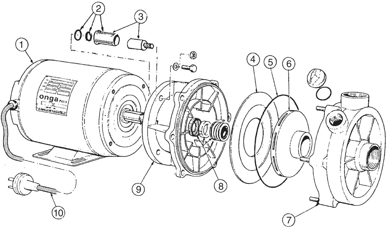
Figure 3.13 A diagram showing the assembly and major components of a centrifugal pump. The major components include: (1) motor; (2/3) shaft sleeve assembly; (4) baffle; (5) ‘O’ ring; (6) impeller; (7) casing; (8) seal; (9) yoke; (10) power lead.
Source: Reproduced with permission from Onga Pty Ltd.
Axial flow pumps are simpler in construction than centrifugal pumps, basically composed of a propeller inside a pipe with a motor‐driven shaft. As described above, these pumps are best for low head, although multistage pumps can create head of up to 40 m, and they are used for high‐volume pumping. The low head pressure of these pumps means that they are not used for pipe distribution, their main use being for discharge into open channels or directly into ponds.
3.4.5 Pump Selection
Apart from, or as well as, using the services of an expert, aquaculturists are required to select the type, make and model of pump, and alternative impeller size and speed, that will suit their system. This decision is aided by performance data for pumps supplied by the manufacturers. For a given pump body, data are presented for a number of different impeller sizes and pump speeds (Lekang, 2013a; Yoo and Boyd, 1994).
Manufacturers will generally provide pump performance data in the form of head/flow capacity (H–Q) curves. H–Q curves are the graphical representation of the flow output of the pump against the total head (friction and elevation forces) against which the pump is acting. The shape of the H–Q capacity curve is critical. The curve must decrease uniformly from the high‐head/low‐flow to the low‐head/high‐flow conditions. If the curve has a flat spot or decreases abruptly at low flow the pump may not work smoothly in this range. In addition to the H–Q curve, the manufacturer’s information will also often include efficiency data, allowing decisions about whether the selected pump will operate near its maximal efficiency in the system. The ‘brake power’ of the pump may also be represented. Brake power represents the power required to operate the pump at a certain flow and head. From this it is possible to determine the operating costs of different pumps by multiplying the operating time (hours) by the brake power for the pump and then multiplying this value by the kilowatt per hour charge of the electricity supplier.
3.4.5.1 Net Positive Suction Head
The net positive suction head (NPSH) and total dynamic head (TDH) are required to determine the size of pump required (Wheaton, 1977; Yoo and Boyd, 1994). The latter will be treated in the next section.
In order for rotodynamic pumps to work, the water must be drawn to the pump under pressure. NPSH is the pressure on the suction side of the pump. The NPSH present within a system is the available NPSH (NPSH‐A). The minimum NPSH required for a pump to operate effectively is the required NPSH (NPSH‐R). NPSH‐A can be calculated using the following formula:

where Ha is atmospheric head (pressure), the pressure of the atmosphere on the surface of the water pushing the water to the pump. Hs is static suction head, the elevation difference between the pump and the water supply. It is negative if the water source is below the pump and positive if the water is above the pump. Hfs is the sum of the frictional losses from the pipe and plumbing on the suction side of the pump. Hvap is the vapour pressure of the fluid.
However, the values required for calculating NPSH‐A are not all fixed, i.e.
- Hfs varies with flow rate and bio‐fouling;
- Hs varies with height of tide, river, reservoir; and
- Ha varies with weather conditions.
For this reason NPSH‐A must be calculated for a range of conditions and be greater than NPSH‐R for all of them, with a safety margin of at least 1 m. Failure to do so is the single greatest source of pumping problems. If NPSH‐R is greater than NPSH‐A, the pump will produce little or no flow or will cavitate because of vaporisation.
TDH is also referred to as system head, differential head, generated head and total head. Total dynamic head is the height difference between the water source and the outlet plus the frictional losses, i.e.
where, Hst is the total static head, the difference between elevation of discharge and water supply; Hft is the total frictional head of pipes, fittings and in‐line components on the suction and discharge sides of the system; and Hv is the velocity head.
When calculating TDH, it is important that the range of flows used in the system is included, as frictional losses in pipes and fittings and the velocity head are proportional to water flow and velocity. Static head will also vary with the height of water in the water source, e.g., with tide height. Determining TDH over the range of flows and static head will enable the ‘working range’ of the pump to be determined.
A pump may be selected after establishing the flow rate, TDH and NPSH‐A requirements.
3.5 Hatchery Systems
Hatcheries are those aquaculture facilities associated with reproduction, larval rearing and supply of juveniles to farms. A single hatchery often supplies a large number of farms, although many aquaculture industries (e.g., the oyster industry) still rely heavily on natural recruitment as a source of culture stock; natural recruitment can be unpredictable and unreliable. As well as providing independence from natural recruitment, other benefits of hatchery production include the potential for genetic improvement of culture stock (Chapter 7) and the reduced potential for conflict with capture fisheries.
Hatcheries have similar site requirements to nursery and grow‐out sites (section 3.2, Lekang, 2013b). Of particular importance is the quality of intake water, which must be free from industrial, urban and agricultural contaminants. The water intake pipe is usually screened to remove foreign items such as seaweeds from intake water. Intake water should also have low levels of suspended solids, to minimise filtration requirements and bacterial contamination, and a temperature as close as possible to that to be used for larval rearing to minimise water heating/cooling costs. A hatchery should also be able to pump water regardless of the state of the tide and should be located close to the farms it supplies.
Marine aquaculture hatcheries may be positioned to use either an oceanic or estuarine water supply. Oceanic water is generally considered to be of higher quality, but such sites may be subject to high wave action and erosion that may lead to problems with water supply. Use of such sites may also result in public resistance on aesthetic grounds. Estuarine water sources are subject to rapid changes in temperature and salinity, which can result from heavy rainfall. Rainfall may also increase levels of suspended solids and bacteria in intake water. Both factors affect water quality and will impact on larval well‐being. Freshwater hatcheries generally use either groundwater (e.g., from an aquifer using a well or bore) or surface water (e.g., streams, rivers and lakes) as water sources. It is important that marine hatcheries also have a reliable source of freshwater for cleaning and washing.
3.5.1 Water Treatment in Hatcheries
Water used for larval rearing is usually treated to reduce particulate matter and bacteria, and heated/cooled to optimise water temperature. Water treatment in hatcheries usually includes the following steps:
- Water storage. Water is usually stored in large tanks (e.g., 20–100 000 L) before being pumped into the hatchery. This also allows suspended solids to settle from the water column.
- Coarse filtration. Water is passed though filtration equipment (e.g., sand filter), which removes larger particles and filters water to around 20 µm.
- Heating. Water may be heated before use. This may be done by heating a common water source or ‘header tank’, from which larval culture tanks are supplied. However, water may also be heated using heat exchange systems, or larval culture tanks may be heated individually using immersion heaters.
- Fine filtration. Before entering larval culture tanks, water is usually passed through fine filtration equipment (e.g., cartridge filters), which filters the water to ~1 µm. This is generally achieved using a series of filters of different sizes in sequence (e.g., 10 µm, 5 µm and 1 µm). Water used for live food culture (e.g., microalgae; section 9.2) is filtered to finer levels of 0.2–0.45 µm.
- Ultraviolet (UV) treatment. Water to be used for larval culture and live food culture may also be passed through a UV steriliser to reduce levels of bacteria. Water must always be filtered to remove suspended particles before being passed through a UV steriliser because particulate matter is the major substrate for bacteria in culture water and high particulate loads will reduce the penetration, and therefore the effectiveness, of the UV radiation into the water.
Additional information relating to the assessment of various water supply systems and water treatment equipment and methods in aquaculture hatcheries is provided by Lekang (2013b). General considerations with regard to water quality and water treatment in freshwater hatcheries for salmonids are given in section 17.3.2.
3.5.2 General Layout of Hatcheries
Although hatcheries differ considerably in layout according to the type of animal propagated, they have a number of common design requirements. These include:
- an area for holding broodstock;
- a dedicated spawning area;
- dedicated food production area(s);
- a dedicated larval rearing area; and
- an area for early nursery culture.
Hygiene is a major concern in aquaculture hatcheries. Disease can be very costly to a hatchery and may result in the loss of live food cultures as well as larvae, juveniles and broodstock. Hatcheries must be designed to minimise the possibility of disease transfer from one area of the hatchery to another, and to facilitate quarantine of a particular area if required. To achieve this, each part of a hatchery should be separated from the others. For example, live foods are usually cultured well away from areas housing culture stock (broodstock or larvae). Larval culture and broodstock holding areas are similarly separated. As well as disease considerations, the isolation of broodstock holding areas minimises noise and other disturbances that may stress the broodstock and impact on reproductive output. Appropriate hatchery design can help minimise the risk of disease and facilitate hatchery efficiency and productivity (Figure 3.8). Some important design considerations include:
- separate access to all hatchery areas;
- antiseptic foot baths between areas to minimise risk of disease transfer;
- larval tanks raised off the ground to allow access for washing or sterilising floor areas;
- well‐drained floors to minimise standing water; and
- air lines, water supply and power located overhead to allow easy access.
3.6 Summary
- The primary objective of aquaculture system design is to ensure that a facility is productive in a reliable and cost‐effective manner. The design of an aquaculture system must allow for maximal growth and survival of the target species and product quality that demands optimal market price. Aquaculture systems must also be reliable and cost‐effective to construct and, from an operator’s perspective, should have minimal operating and maintenance requirements.
- Culture structures describe what encloses or supports the aquaculture organisms. Broadly, aquaculture structures include ponds, tanks, raceways, cages, pens, racks, long‐lines and floats.
- Water exchange describes the amount of water exchanged or the level of control over water flow to the system. Broadly, the levels of water exchange are static, open, semi‐closed and recirculating (closed).
- Although hatcheries differ considerably in layout according to the type of animal propagated, they have a number of common design requirements. They should include an area for holding broodstock, a dedicated spawning area, dedicated food production area(s), a dedicated larval rearing area and an area for early nursery culture.
References
- Beveridge, M., 2004. Cage aquaculture. Blackwell Publishing.
- Boyd, C.E., 1995. Bottom soils, sediment, and pond aquaculture. New York, USA. Chapman & Hall, 366.
- Boyd, C.E., Tucker, C.S., 1998. Pond aquaculture water quality management. Springer Science & Business Media.
- Cardia, F., Lovatelli, A. 2015. Aquaculture operations in floating HDPE cages: a field handbook. FAO Fisheries and Aquaculture Technical Paper No. 593. Rome, FAO. 152 pp.
- Fitridge, I., Dempster, T., Guenther, J., de Nys, R., 2012. The impact and control of biofouling in marine aquaculture: a review. Biofouling,28, 649–669.
- Landau, M., 1992. Introduction to aquaculture. Wiley, New York.
- Lekang, O.I., 2013a. Aquaculture Engineering, 2nd ed. Wiley Blackwell, UK.
- Lekang, O.I. 2013b. Aquaculture hatchery water supply and treatment systems. In: Allan G., Burnell, G. (Eds.) Advances in Aquaculture Hatchery Technology. Woodhead Publishing, Oxford. 3–22 pp.
- Losordo, T. M., Masser, M. P. & Rakocy, J. 2001. Recirculating aquaculture tank production systems. An overview of critical considerations. World Aquaculture, 32, 18–22.
- Pierce, R.H., Weeks, J.M., Prappas, J.M., 1993. Nitrate toxicity to five species of marine fish. J. World Aquacult. Soc.,24, 105–107.
- Quayle, D., Newkirk, G., 1989. Farming bivalve molluscs: methods for study and development. World Aquaculture Society in association with the International Development Research Centre.
- Wang, J., Fast, A., 1992. Shrimp pond engineering considerations. Dev. Aquac. Fish. Sci., 23, 415–429.
- Wheaton, F.W., 1977. Aquaculture Engineering. Wiley, New York (reissued, 1993).
- Wyban, J., Sweeney, J., 1989. Intensive shrimp growout trials in a round pond. Aquaculture, 76, 215–225.
- Yoo, K.H., Boyd, C.E., 1994. Hydrology and water supply for pond aquaculture. Springer Science & Business Media.