Chapter 1. Introduction to Blender
In this chapter, we will look at the basics of using Blender in order to build a foundation for our work in later chapters. We’ll explore its user interface, how to navigate the 3D Viewport, and how to add and interact with objects. Throughout this chapter, I’ll point to later parts of the book, where various topics will be covered in greater detail. If you are already comfortable with Blender, feel free to skip to Chapter 2, on GIMP, or Chapter 3, on preparing your projects.
About Blender
Blender is a free open source 3D design and animation package, available for Windows, Linux, and Mac OS X. Originally created as an in-house animation package for Dutch animation studio NeoGeo, it was later released under the GNU General Public License when its developer, NotANumber, went bankrupt and the Blender community raised €100,000 to pay creditors to release the Blender source code.
Since then, Blender has undergone continued development by the Blender community, overseen by the Blender Foundation (headed by Ton Roosendaal, one of the original developers of Blender). The current version (Blender 2.6x, as this book goes to press) boasts a wide array of features competitive with many commercial 3D applications and has a committed and enthusiastic community creating art and animation with it.
Blender is used today by many animation studios, game developers, artists, and hobbyists. It has been used to make feature films, short films, and games. Of particular note are the Blender Foundation’s open movie projects—community-funded short film projects that are used to drive the development of Blender forward by using it in a production environment. To date, four short films and one game have been completed, each yielding significant improvements and new features in Blender’s repertoire. The first short film, Elephants Dream, premiered in 2006. It’s a surreal tale in which two characters travel through a bizarre mechanical world. It introduced particle-based hair and fur rendering, as well as new animation tools and improvements to Blender’s render engine. In 2008, Big Buck Bunny introduced improvements to fur rendering, particles, and the render pipeline, as well as more advanced rigging and animation constraints. In 2010, Sintel, a tale about a girl and her dragon, brought advanced sculpting tools, new simulation tools, and shading and rendering improvements.
The latest open movie, Tears of Steel, focused on adding advanced visual effects tools to Blender. It brought major improvements to the new Cycles render engine and has introduced camera tracking tools, new features for Blender’s compositor, improved simulation tools, and better color management.
Current, stable Blender builds for Windows, Linux, and Mac OS X are available from http://www.blender.org/. In addition, you can find development builds featuring the latest updates from http://www.graphicall.org/. These development builds are designed for more advanced users or those who wish to try new features; they can be unstable, so stick with the official builds for important work.
The Blender User Interface
Blender’s user interface (UI) has earned a reputation for being difficult to grasp. In earlier versions, this reputation was somewhat justified, but since Blender 2.5, the interface has seen major updates and is now much more predictable and easier to learn. Plus, with the addition of the search function, if you have trouble finding a particular operator, you can search for it by pressing the spacebar to bring up a search dialog in which you can search for operators by name.
Once you have grasped the UI, you’ll find that Blender is very fast and extremely customizable. Most functions have keyboard commands for quicker access, and the interface is non-blocking, which means that windows and dialogs won’t be layered on top of one another, obscuring your view.
Layout and UI Terminology
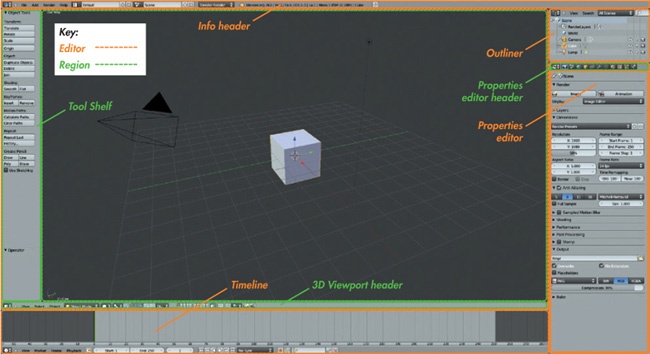
When you first start Blender, the default layout should look something like Figure 1-1. The Blender window is broken into areas called editors. These editors include the 3D Viewport, the Properties editor, the Outliner, the Info editor, and the Timeline, as shown in Figure 1-1.
Editors are further broken down into regions. In the case of the 3D Viewport in Figure 1-1, the regions are the Main region (that is, the 3D view), the Header region at the bottom of the editor, and the Tool Shelf on the left.
Regions that contain buttons and properties—like the Properties editor or the Tool Shelf in the 3D Viewport—are further broken down into panels. A panel may contain any number and combination of operator buttons, information, and properties. The panel’s name is shown at the top of the panel (see Figure 1-2) and indicates what sort of properties and information the panel contains.
Switching Editors and Customizing the UI
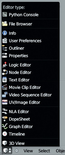
Blender’s UI layout is highly configurable. You can switch any editor in the current layout to a different editor type by selecting a new one from the drop-down menu at the far left of the Header region (see Figure 1-3).
You can also resize existing editors and add or remove editors by splitting or merging existing ones. To resize an editor (or a region), click and drag on its border. To split or merge editors, right-click the editor’s border and choose either Split Area or Merge Area. (In later chapters, we’ll use this technique to adjust Blender’s layout to better suit various stages of each project.)
Multiple Layouts
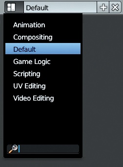
Because different UI layouts are suitable for different tasks, Blender allows you to store multiple UI layouts so that you can switch between them as you work. To switch layouts, click the screen layout drop-down menu in the Info editor header (see Figure 1-4).
By default, Blender includes layouts named Animation, Compositing, Default, Game Logic, Scripting, UV Editing, 3D View Full, Motion Tracking, and Video Editing, each of which is pretty well suited to the task that it’s named for. (Default is the default layout when you start Blender and is good for modeling.) To add your own layout, click the + icon at the right of the drop-down menu to copy the current layout and modify it, or delete the current layout by clicking the X icon. Layouts are saved along with your .blend file when you save your work, so you can return to them when you reopen the file.
You can make a layout available by default by saving it as part of the default .blend file, the file that is loaded upon starting Blender. To do so, load the default .blend file (CTRL-N) and then create the layout you want using the methods outlined above. Use CTRL-U to save the current file as the new default start-up file. (To restore the original default .blend file, select Load Factory Settings from the File menu and then save the default .blend file again.)
Editor Types
Each of Blender’s editors offers a different functionality. Not all editors will be useful to us in the course of this book, so I will discuss just those that are relevant to the projects we’ll tackle.
The 3D Viewport
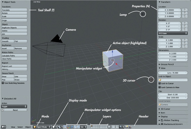
This is Blender’s most important editor type. The 3D Viewport (see Figure 1-5) is where you can view your scene and its objects and then move, manipulate, and organize them.
The 3D Viewport has four regions: the main 3D view; the Header, which is found either at the top or bottom of the editor (usually the bottom); the Tool Shelf; and the Properties region, the last two of which can be hidden with the hotkeys T and N while the mouse is over the 3D Viewport editor.
Navigating the 3D Viewport
It’s very important to learn to navigate the 3D Viewport, and there are several ways to do so. The simplest is with the mouse. Scrolling the mouse wheel zooms in and out, holding the middle mouse button rotates the view, and SHIFT-middle mouse button pans the view. To center the view on the currently selected object, press NUMPAD. (period), and to reset the view to center on the scene’s origin, press SHIFT-C.
Note
Blender treats the number pad keys and the corresponding keys on the keyboard differently. For example, the number pad (numpad) numbers are used for navigating the 3D view, while the character key numbers are used to toggle visibility of different scene layers.
You can also snap the viewpoint to specific angles using the number pad. NUMPAD 7 snaps to top-down view, NUMPAD 1 snaps to front view, and NUMPAD 3 snaps to side view. NUMPAD 5 switches between a perspective view, where objects in the distance appear smaller (as in real life), and an orthographic view, where objects appear the same size at all distances. When combined with the top, side, and front views, orthographic view is most useful for aligning objects precisely.
The 3D Viewport has multiple display modes that can be selected from the 3D Viewport header (see Figure 1-5). These viewing modes include the default solid view; wireframe; bounding box, which represents objects as simple boxes instead of displaying their geometry; and textured view, which can display shading and texturing. In later chapters, we’ll look at customizing the 3D Viewport for different purposes, including using different textured shading modes and working with layers and hiding objects.
Coordinates in 3D and the Grid Floor
If you haven’t dealt with 3D graphics before, you may not have thought about how to define a point in space. Of course, 3D models are essentially created by connecting points in space. Thankfully, French philosopher and mathematician René Descartes gave us a solution to this problem several centuries before we got around to inventing computers and 3D graphics.
To define a point in 3D space, we need information about the point’s position in each spatial dimension in relation to a reference point. In Blender, this information comes in the form of the point’s x-, y-, and z-coordinates, which indicate the point’s position along three axes that run perpendicular to one another. These are called Blender’s global coordinates. The reference point we use is called the scene’s origin—the point whose coordinates for each of the axes is zero.
By convention, we generally think of the x-axis as being the “left–right” axis, the y-axis as the “forward–back” axis, and z-axis as the “up–down” axis. (The different viewpoints given by the keyboard shortcuts mentioned above conform to this convention—the top-down view looks downward along the z-axis, and so on.)
You can see the x- and y-axes in Blender’s 3D Viewport as red and green lines, respectively. Extending from these lines in light gray is the grid floor, which we generally use as the ground height of the scene when placing objects. The divisions of the grid are all 1 Blender unit apart by default, giving you a guide to use for placing objects and judging their size. The x- and y-axes and the grid floor are also useful when orienting yourself in Blender’s 3D Viewport.
The Properties Editor
The Properties editor is where you can define the settings and properties for a scene or a selected object. The Properties editor is divided into Header and Main regions, with the Main region being split into tabs (as shown in Figure 1-2). Each tab contains a different set of properties that relates to either the current scene or the active object. In order of appearance, the tabs are as follows:
Render. The Render tab contains settings for rendering your scene, including render dimensions, shading options, and output formats. (We’ll discuss this in more detail in Chapter 14.)
Scene. The Scene tab lets you set the properties of your scene, such as the active camera, certain sound settings, and the scene’s units (arbitrary Blender units, imperial, or metric).
World. The World tab lets you define the scene’s background, as well as the world lighting options, such as environment lighting and ambient occlusion. (We’ll discuss this in more detail in Chapter 13.)
Object. The Object tab (see Figure 1-2) lets you set an object’s transformations manually by using numerical values rather than moving the object about in the 3D Viewport. You can manage an object’s group membership as well as how it is displayed. (We’ll use groups in Chapter 9 to duplicate multiple objects using particle systems.)
Object Constraints. The Object Constraints tab contains an object’s constraints stack. This is useful for animation but not a topic that we’ll cover. (See the Blender wiki at http://wiki.blender.org/ for more on constraints.)
Object Modifiers. This tab contains an object’s modifiers stack and lets you add new modifiers. Modifiers are procedural, nondestructive methods for manipulating and generating a mesh’s geometry. As you add new modifiers to an object, they are applied in the order they appear in the stack (from top to bottom). (We’ll discuss modifiers in more detail in Chapter 4 and Chapter 5.)
Object Data. The Object Data tab lets you set which datablock the active object uses and exposes the different sets of data assigned to this datablock (see Datablocks). The contents of this tab vary according to the object’s type. For example, in the case of a mesh object, this tab will display the mesh’s vertex groups, shape keys, and UV coordinate sets, whereas for a lamp object, it will contain the lamp’s color, energy, and shadow settings. The icon for this tab also changes to match the active object’s type: For mesh objects, the icon is a cube; for lamps, a light; and so on. The Object Data tab will come up throughout this book.
Material. The Materials tab displays an object’s material slots and the materials assigned to them. Here, you can edit the basic properties of the materials you create, turn on or off different shading options, and adjust the properties of an object’s material.
Textures. The Textures tab complements the Materials panel. It lets you assign textures to a material, define how textures affect the properties of a material, and determine how they are mapped to an object’s surface. (We’ll cover this tab in more detail in Chapter 12.) You can also use the Textures tab to assign textures to your world background or to particle systems.
Particles. The Particles tab allows you to assign particle systems to an object and define their properties. Blender has two kinds of particle systems: dynamic emitter particles and hair particles. In Chapter 9, we’ll discuss using hair particles to create hair, fur, and foliage, and we’ll review the settings for hair particles in more detail.
Physics. The Physics tab contains tools for simulations, allowing you to simulate smoke, fluids, cloth, and rigid and soft body physics. (Learn more about these options on the Blender wiki.)
The Info Editor
The Info editor (see Figure 1-6) looks like a regular menu bar, but it’s actually an editor, like the 3D Viewport and the Properties editor. It’s usually kept scaled down to show just the header, which is its most important part. The header contains various menus, including the File menu, the Help menu, and menus for adding objects and rendering.
The drop-down menu selectors to the right of these menus let you change the window layout (discussed above) and the current scene (discussed in Scenes). Next to these selectors, a drop-down menu allows you to select which render engine to use. (See Chapter 12, Chapter 13, and Chapter 14 for discussions of Blender’s two native render engines.)
After the render engine drop-down menu, you’ll find several pieces of information, including the version of Blender you are using and some information about the scene. From left to right, the scene information includes the vertex count (Verts); face count (Faces); number of objects in the scene (Objects); number of lamps (Lamps); the scene’s memory consumption; and the name of the currently selected object.
If you drag down the border of the Info editor, you will see that Blender uses the rest of the editor to provide a log of your actions as Python commands. This information provides a glimpse into the behind-the-scenes workings of Blender’s Python API (application programming interface) as you work, and it can be most helpful when creating Python scripts. However, since we won’t need Blender’s scripting features for any of the projects in this book, it can remain hidden most of the time.
The Node Editor
The Node editor is a multipurpose editor for anything that is (or can be) constructed with nodes. This includes the compositor, which uses nodes by default, as well as node materials and textures, which may or may not be node based. You can switch between viewing Blender’s various node setups by clicking icons in the Node editor’s header (see Figure 1-7). The header’s main region displays the current node setup on a grid, allowing you to add, delete, or move nodes and to view and edit their connections.
We’ll look at the Node editor in more detail in Chapter 12 when we create node-based materials for the Cycles render engine and in Chapter 14 when we create node trees for compositing.
The UV Image Editor
The UV Image editor is the 2D equivalent of the 3D Viewport. Here, you can view images (Image ▸ Open Image from the header or select an already loaded image from the image selector drop-down menu) and edit the UV coordinates of unwrapped meshes. While rendering, Blender displays the current render in a UV Image editor. Use the drop-down menu to view the most recent render or to view the viewer outputs of compositing node trees. We’ll discuss the UV Image editor in more detail in Chapter 3, Chapter 8, Chapter 10, Chapter 11, and Chapter 14.
Other Editors
Blender has several other types of editors. We’ll cover some in this book, but we’ll leave out ones like the Graph editor, which is tailored to animation, and the Logic editor, which is tailored to Blender’s game engine. For more on these editors, see the Blender wiki (http://wiki.blender.org/).
Using Blender
Now that we have some knowledge of Blender’s UI, we can learn how to actually use Blender. We’ll look at the default .blend file and then explore working with objects in the 3D Viewport and the Properties editor. We’ll also examine how Blender files are constructed, which will help us when working on our projects.
Scenes
There is a hierarchical structure to .blend files (see Datablocks), at the top of which is a scene. A .blend file can contain one scene or many. Each scene is its own separate 3D space where you can create objects and build your project, and each scene has its own settings that define how it is rendered.
The current scene is shown in the info header at the top of the Blender window, next to the current layout (see Figure 1-8). To create a new scene in a .blend file, click the + icon to the right of the current scene’s name. Blender will ask you whether you want to create an empty scene or copy data from the current one. Although it can be useful to create extra scenes when working with more complex projects, we’ll use one scene per .blend file for each project in this book.
The Default .blend File
When you first open Blender, you are presented with a single, simple scene (as shown in Figure 1-1). By default, this scene contains three objects: a cube, a lamp, and a camera. These objects are all that is required to get a simple render of something more than a blank background. The camera tells Blender what viewpoint it should render, the cube provides something for the camera to view, and the lamp illuminates the cube and makes it appear as more than a simple black silhouette.
However, a gray cube on a gray background doesn’t make for the most interesting of renders. To create something more interesting, we need to create our own objects to replace these rather dull ones.
Adding Objects
To add an object to your scene, place your cursor over the 3D Viewport and press SHIFT-A to bring up the Add menu. Here, you can add any object type that Blender supports, including meshes, curves, empties, lamps, cameras, and so on. (We’ll discuss these object types as we progress through the book.)
The 3D Cursor
New objects will be added at the location of the 3D cursor, which is Blender’s easily configurable way of quickly defining a point in space. The 3D cursor (shown in Figure 1-9) is where new objects will be added by default. You can also set transform operators, such as rotation and scaling, to use the 3D cursor as the pivot or origin point for the operator.
By clicking within the 3D Viewport, you can move the 3D cursor to wherever you click (the cursor’s distance from your viewpoint will remain the same). You can also move the 3D cursor by changing its location values in the 3D Cursor panel of the Properties region of the 3D Viewport. (If you lose the 3D cursor or simply want to reset it to the scene’s origin, press SHIFT-C to reset the 3D Viewport’s view and place the 3D cursor at the scene’s origin.)
Selecting Objects
To select an object, right-click it. To select multiple objects, SHIFT-right-click them. Selected objects are outlined in orange by default. The most recently selected object is called the active object and is outlined in brighter orange than the rest of your selection. The properties of the active object are the ones that will appear in the Properties editor. Most operators use or act on the active object, though some act on your whole selection.
Manipulating Objects
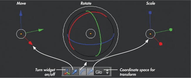
There are several ways to manipulate objects in the 3D Viewport. Perhaps the simplest way is to use the keyboard shortcuts: G to move, R to rotate, and S to scale. You can also use the manipulator widget (see Figure 1-10) to manipulate objects by clicking and dragging one of its three handles to manipulate one axis or by clicking and dragging the white circle in the middle to manipulate the object on any axis.
By default, the manipulator appears as three colored arrows. Click and drag on the arrows to move your selected objects in the directions they point (along the global x-, y-, and z-axes by default). Use the icons in the 3D Viewport header to have the manipulator widget let you rotate or scale objects instead of move them (see Figure 1-10).
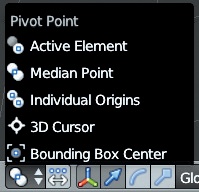
By default, when in Object mode, Blender uses the object’s local coordinate origin (see Figure 1-11) as the position of the manipulator widget. To change the pivot center of an operator, use the Pivot Center option in the 3D Viewport header. You can switch between using the median point of the selected objects origins (the default), the origin of the active object, the individual origins of each object in your selection, the 3D cursor, and the center of a hypothetical bounding box drawn around all selected objects. This not only moves the manipulator widget but also uses the selected pivot center for any transformations or operators you do using keyboard shortcuts or the mouse.
In Chapter 4 and Chapter 5, we’ll examine manipulating objects, meshes, and curves in more detail.
Other Coordinate Systems
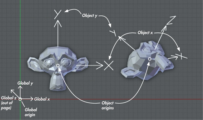
The coordinate system described in Coordinates in 3D and the Grid Floor is defined relative to the scene’s origin, and its coordinates are referred to as global coordinates. These are universal to the scene. However, objects also have their own individual coordinate systems and their own origins (the latter being indicated by a small orange circle when you have the object selected). These coordinates are called the object’s local coordinates, and they may match up with the scene’s global coordinates or they may not (see Figure 1-12). For example, when you move an object in Object mode, you move its local coordinate origin along with it, and when you scale or rotate it, you scale or rotate its local coordinate axes. This may sound confusing, but it has an important purpose. The positions of the vertices of a mesh (that you can edit in Edit mode) are defined relative to the object’s local coordinates. This means that however you move, scale, or rotate an object in Object mode, the mesh’s vertices remain unchanged in terms of their local coordinates. We’ll use this to our advantage later when creating multiple duplicates of objects, which will share the same mesh data and local coordinates but also be able to be scaled and rotated independently of one another in Blender’s global coordinates.
In Figure 1-12, two identical monkey head meshes have been created. The first has been moved in Object mode so that its origin is no longer at the global origin, but its axes still point in the same directions as the global coordinate axes. The second has been moved and also rotated so that neither its origin nor the directions of its local coordinate axes match up with the global coordinates. With respect to the objects’ meshes, however, the local coordinates still point in the same directions—the y-axis out of the top of the monkey’s head and the x-axis out from its left ear.
You can view an object’s local coordinates by going to the Object tab of the Properties editor and enabling the Axis setting in the Display panel.
Operators
Translation, rotation, and scaling are among the simplest ways to interact with an object. Other simple ways include deleting an object (X), hiding it (H), or duplicating it (SHIFT-D). These and similar actions are all operators. We’ll cover a much greater range of operators in Chapter 4 when we begin modeling, and we’ll continue to expand this repertoire of operators throughout the book.
Datablocks
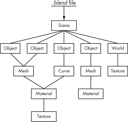
Everything in Blender is built out of datablocks, which are simply chunks of data. All of Blender’s objects, meshes, materials, textures, and images are different types of datablocks. Even the scene itself is a datablock that points to the datablocks that make up its contents.
Datablocks are arranged hierarchically. For example, a scene datablock will contain object datablocks, which reference mesh datablocks. Mesh datablocks, in turn, reference material texture blocks, and so on. This structure is shown in Figure 1-13.
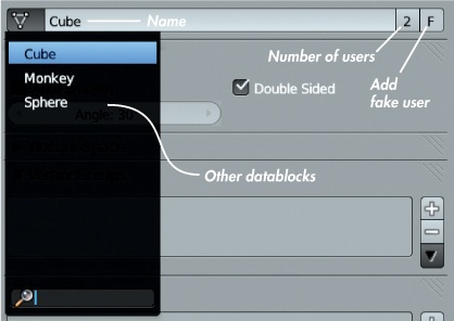
The top of the Properties editor’s Object Data tab displays the datablock used by the active object. Click the icon to the left of the datablock’s name to change the datablock used (see Figure 1-14).
Defining objects as datablocks allows you to easily copy and duplicate objects within Blender. For example, you can create a regular duplicate by pressing SHIFT-D, which creates a new object with a copy of the original’s datablock. (You can edit this duplicate without affecting the original.) You can also create a linked duplicate with ALT-D. The linked duplicate uses the same datablock as the original, which means that when you edit one duplicate, the other is updated identically. (We’ll use this technique in later chapters to save time when working on multiple copies of the same object.)
The same goes for other kinds of datablocks. For example, in the case of materials and textures, you can assign the same material to multiple objects or the same texture to multiple materials, to save time and to avoid having to create unique materials and textures for every object. Of course, this feature also means that we have to keep track of which object is using which datablocks and how many users a datablock has. To see how many users a datablock has, look next to its name in the drop-down menu where it is selected. Datablocks with multiple users will show how many users they have to the right of their name (see Figure 1-14). (Click this number to make a new, unique copy of that datablock.)
Datablocks with no users are deleted when you quit Blender. To keep a datablock that has no users, such as a material you might want to reuse or an earlier version of a mesh datablock, protect it by clicking the F icon next to the datablock’s name (see Figure 1-14). This creates a “fake” user so that the datablock will be saved along with your file.
Naming Datablocks
To rename a datablock, click its name. When naming datablocks, it’s good practice to give them descriptive names to make it easier to pick a particular datablock from a list. Renaming your datablocks with descriptive words, such as Wood, Red Paint, Skin, and so on, will make your scene easier to navigate and understand later on.
Modes
Blender has different modes for editing the different aspects of an object’s data. The default is Object mode, which lets you add and delete objects and also move, scale, and rotate them. Other modes let you edit mesh data and particle systems, sculpt on meshes, paint textures, and adjust vertex group weights.
Blender’s two most important modes are Object and Edit mode. To switch between them, use the hotkey TAB. To access other modes, click the Modes drop-down menu in the header of the 3D Viewport (see Figure 1-5) and select the mode you want.
In Chapter 4 and Chapter 5, we’ll use Edit mode extensively for modeling, and in Chapter 6, we’ll use Sculpt mode. Then in Chapter 8, we’ll use Particle mode and Weight Paint mode to create and comb particle hair and paint vertex groups for controlling fur. Then, in Chapter 11, we’ll use Texture Paint mode to paint textures on our models.
Saving and Loading
Saving and loading in Blender works much the same way that it does in any application. Use File▸Save (CTRL-S) to save and File▸Open (CTRL-O) to open a file.
Blender saves files in a unique .blend format. By default, external files, such as images loaded into Blender, are not saved along with the .blend file but are referenced relative to the file. Thus, to open a .blend file on another computer, you need to copy over the .blend file plus all the other files it references and re-create the same directory structure before opening the .blend file. Alternatively, you can “pack” your .blend file, which saves external data such as images within the .blend file, so that you can then open up the .blend file on any machine and have all the data it needs.
Appending and Linking
Blender lacks the standard copy-and-paste functionality for objects or other kinds of datablocks that you might expect from using more conventional applications. To copy an object, you can either duplicate it or simply reference the same datablock using an existing object. But what if you want to bring something in from an external .blend file?
That’s where the Append and Link features come in. Appending and linking let you bring datablocks from one .blend file into another. Append (File▸Append) brings the datablock wholly into the current .blend file as an independent copy of the original. Linking (File▸Link) references the original datablock in the other file. Linked datablocks cannot be edited in the .blend file they are linked into; rather, they must be edited in the original file.
Appending is useful for quickly bringing an existing resource into your .blend file so that you can use and edit it. Linking is useful for combining multiple elements in larger projects when, for example, different people are editing various parts independently. By linking all the elements of a project into one scene, people can work on parts independently in separate .blend files, while keeping the final assembly of multiple linked objects up-to-date. (If you link a datablock and wish to edit it locally, make it into a local datablock using the Make Local operator (L).)
In Review
This chapter has offered a basic introduction to Blender. You’ve learned the basics of how to work with Blender’s user interface and essential tools. We looked at its UI terminology and its different editor types, explored the basics of adding and manipulating objects, and discussed how objects and datablocks work in Blender. We also looked at how to save and load files and import elements from one .blend file into another.
In the next chapter, we will move on to learning a little about GIMP, a free open source image-editing program that makes an ideal companion to Blender when you’re working on projects.
