9.1 Motion artifacts
Motion artifacts occur as a result of movement of tissue during the data acquisition period. They are manifest as signal misregistrations in the phase encoding direction, though the specific appearance of the artifact depends on the nature of the motion and the particular measurement technique. The artifacts are caused by tissue that is excited at one location, producing signals that are mapped to a different location during detection. As mentioned in
Chapter 4, the typical MRI scan excites and detects a signal from a tissue volume multiple times with the phase encoding gradient

changing amplitude prior to signal detection. The assumption is made that any measured signal intensity variations from one measurement to the next are as a result of

only. When tissue moves, the protons are at a different location at the time of detection and experience a different

amplitude, contributing a different frequency and phase for that measurement. The Fourier transformation mismaps these protons to an incorrect location along the phase encoding direction in the image. The misregistered signals occur along the phase encoding direction rather than the readout direction because

is identical for each signal that is measured, while

changes from line to line. In addition, the encoding of phase by

occurs prior to signal detection while it occurs concurrent with signal detection for

. In general, many measurements are made in the production of an image, each with a different amount of motion contamination.
The sensitivity of a measurement to tissue motion depends on the amount of frequency and phase variation that occurs between successive echoes due to the tissue movement. If the motion occurs during measurements with high positive or negative

(at the edges of

), then the misregistered signal will have very little amplitude and will generate minimal artifact regardless of the nature of the motion. If the motion occurs during measurements with low amplitude

(low magnitude

), the nature of the motion and the measurement technique will affect the artifact appearance. If the echo timing is relatively slow or the motion is at a moderate rate, significant artifact will be generated since there will be significant signal measured from different locations. If the time between successive echoes (echo spacing in echo train sequences,
TR for traditional sequences) is rapid and the motion is relatively slow, the echoes near the center of

may be acquired with the tissue in the same location, so that there is minimal artifactual signal generated. This is the principle behind the use of single-shot ETSE for visualizing the small bowel.
The artifact appearance also depends on the nature of the motion. If the motion itself is periodic, then the misregistration artifacts will be discrete in nature, often referred to as “ghosts”. The “ghost” signals will offset in the phase encoding direction from the primary anatomy at locations inversely proportional to the difference between the period of the motion and the
TR of the scan. The sequence looping may also affect which images of the scan will show motion artifacts, subject to the

discussion above. For scans with one subloop, all images will generally exhibit motion artifacts. For scans with multiple subloops, artifacts will be present for all images within a subloop where the motion occurs. When interleaved acquisition ordering is used, images at adjacent slice positions may show different amounts of artifact contamination.
Probably the most common motion artifact in MRI is due to blood flow. The artifact from blood flow is dependent on the nature of the flow and its direction relative to the slice orientation. Through-plane flow (flow that is perpendicular to the slice plane) typically produces a localized artifact in the image with a width equal to the vessel diameter and in line with the source of the flow. Flow that is relatively fast compared to
TR will produce a relatively continuous artifact throughout the FOV, such as in spin echo images (
Figure 9.1a). Flow that is slow relative to
TR may not generate an artifact as significant saturation will occur unless a contrast agent is used to shorten the
T1 relaxation time of the blood. If the flow is relatively periodic such as pulsatile flow, then the artifact appears as “ghost” vessels at discrete intervals. This is often seen from blood flow in the aorta or inferior vena cava (IVC) in transverse slices of the abdomen acquired with gradient echo images (
Figure 9.1b). In-plane flow (flow that is parallel to the slice plane) produces a more diffuse artifact, which can be observed from the aorta and IVC in coronal images. The vessel extends through the entire image field and thus the artifact affects all regions of the image (
Figure 9.2a). Flow of the cerebrospinal fluid in the brain and spinal canal are also problematic and can produce analogous artifacts on
T2-weighted images (
Figure 9.2b).
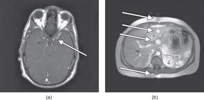
Figure 9.1 Flow misregistration artifact, through-plane. (a) Flow fast compared to measurement technique produces “zipper”-like artifact (arrow). Measurement technique: pulse sequence, spin echo; TR,  ; TE,
; TE,  ; acquisition matrix,
  , 192 and
  ; FOV, 172 mm PE × 230 mm RO;
  , 1; slice thickness, 5 mm. PE direction: R–L; RO direction: A–P. (b) Periodic flow from the aorta will be misregistered as multiple ghosts (arrows). Measurement parameters are: pulse sequence, two-dimensional spoiled gradient echo; TR,
  ; TE,
; TE,  ; excitation angle, 70°; acquisition matrix,
  , 134 and
  ; FOV, 262 mm
  ;
;  , 1; slice thickness, 5 mm; PE direction, A–P; RO direction, L–R.
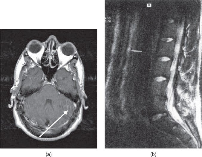
Figure 9.2 Flow misregistration artifact, in-plane. (a) In-plane blood flow will produce severe signal misregistration (arrow). Measurement technique: pulse sequence, spin echo; TR,  ; TE,
; TE,  ; acquisition matrix,
  , 192 and
  , 256; FOV,
  ;
;  , 1; slice thickness, 5 mm; PE direction: R–L; RO direction: A–P. (b) Flow misregistration artifact. Flowing CSF will be misregistered as a ghost canal (arrow). Measurement parameters are: pulse sequence, spin echo; TR,
  ; TE, 90 ms; excitation angle, 90°; acquisition matrix,
  , 192 and
  , 256 with twofold frequency oversampling; FOV,
  ;
;  , 1; slice thickness, 5 mm; PE direction,
  ; RO direction,
  .
.
In abdominal or lumbar spine imaging, respiratory motion and peristalsis are the most common causes of a severe artifactual signal. The movement of the abdomen during the data collection process produces multiple misregistration artifacts. If the respiration rate is constant, the “ghost” images are either few in number or discrete and offset in the phase encoding direction from the true image by an amount proportional to the respiration rate.
If the respiration rate is variable, the “ghost” images are numerous and appear as a smearing of signal throughout the entire image (
Figure 9.3a). For segmented techniques such as echo train spin echo techniques, respiratory motion may appear as multiple lines or so-called “venetian blinds” superimposed throughout the entire FOV in the phase encoding direction. The number and spacing of the lines is based on the number of segments for the scan (
Figure 9.3b). Peristalsis produces motion artifacts that are less distinct than those from respiratory motion. In most instances, a general blurring of the large and small bowel occurs and a layer of noise is superimposed over the entire image.
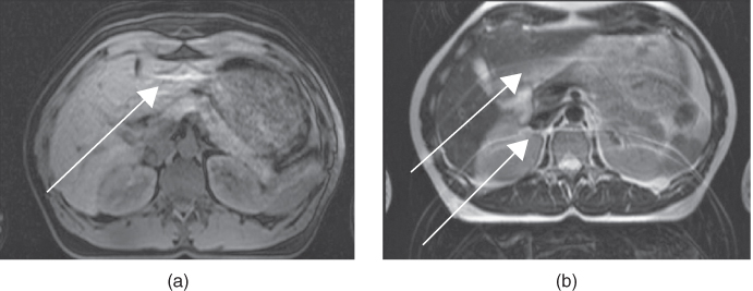
Figure 9.3 Respiratory motion artifact. Extraneous ghost images are generated due to motion of the abdominal wall during data acquisition (arrows). The number and severity of the ghosts depends on the TR, respiration rate, and the particular measurement technique. (a) Pulse sequence, two-dimensional spoiled gradient echo; TR, 159 ms; (b) pulse sequence, echo train spin echo; TR, 4000 ms.
9.3 External artifacts
External artifacts are generated from sources other than patient tissue. Their appearance in the final images depends on the nature of the source and the measurement conditions. The sources may be classified into two general categories: those originating from a malfunctioning or miscalibration of the MRI hardware and those that are not. Excluded from this group are hardware problems that cause complete failure of data collection or image reconstruction. Manufacturers exert great effort to ensure that the acquired images faithfully represent the MR signals from the defined area of interest. The artifacts described here are not specific to any particular manufacturer, but can occur on any MR system.
9.3.1 Magnetic field distortions
One of the most common system-related problems is produced by static distortions of the main magnetic field. These distortions may be due to causes related to the magnet environment or to the patient. They can cause contrast variations within the image, particularly when fat saturation is used. External causes may be transient in nature or permanent. Transient causes are typically due to unattached metal inside or near the magnet bore. These may be items such as metal clips or hooks on clothing, or staples or other removable objects. Also, items such as wheelchairs or gurneys may have metal components that alter the magnetic environment and thereby distort the magnet homogeneity. These sources can easily be eliminated by removing the metal from the vicinity of the bore. Permanent distortions to the magnetic field can be caused by metal structures surrounding the magnet (e.g., walls, cabinets) or due to manufacturing imperfections within the magnet itself. During system installation, manufacturers perform a field optimization procedure known as shimming (see
Chapter 14) to eliminate coarse distortions of the central magnetic field caused by the permanent structures.
Magnetic field distortions related to the patient are typically of two types. The presence of the patient inside the magnet bore will distort the magnetic field, due to a nonuniform shape and tissue susceptibility. The other source of distortion arises from metal implants. They will deform the local magnetic field homogeneity surrounding the implant, producing significant artifacts. These artifacts frequently appear as an expansive rounded signal void with peripheral areas of high signal intensity distorting the surrounding regions, termed a “blooming” artifact. The size and shape of the artifact depends on the size, shape, orientation, and nature of the metal and the pulse sequence used for the scan (
Figure 9.19). Titanium or tantalum
produce very localized distortions, while stainless steel can produce severe distortions that may compromise the images (
Figure 9.20). All echoes are affected by the presence of the metal.
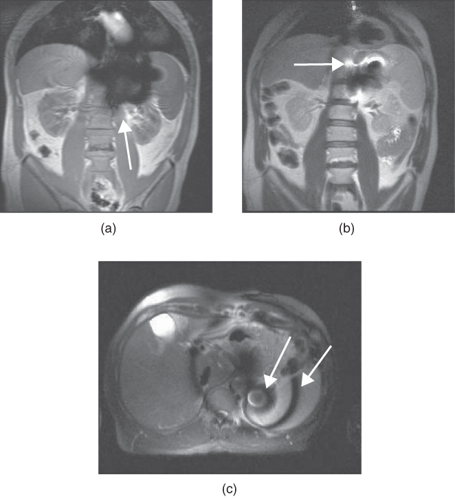
Figure 9.19 Magnetic susceptibility difference artifact. Surgical clips produce a void of signal caused due to the significant magnetic field distortion. (a) Spoiled gradient echo sequence shows significant signal distortion (arrow). (b) Single-shot echo train spin echo at the same level shows less signal loss (arrow). (c) Single-shot echo train spin echo with fat saturation shows incomplete saturation due to field distortions (arrows).
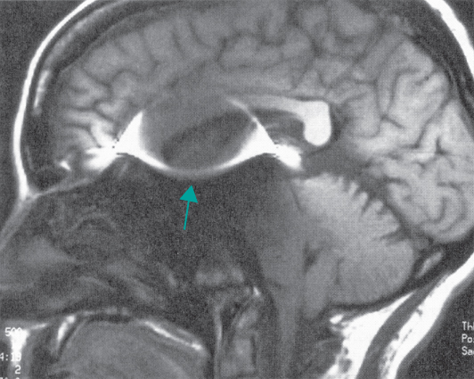
Figure 9.20 Stainless-steel aneurysm clip produces severe field distortion. Pulse sequence: spin echo.
The amount of image distortion observed from static field inhomogeneities also depends on the specific measurement technique. If the field homogeneity disruption is severe, the signal loss will be enough to preclude any image whatsoever. In general, gradient echo sequences are most sensitive to field distortions. This is due to the echo signal amplitude being a function of T2*, in which proton dephasing from magnetic field inhomogeneities is a significant factor affecting the image contrast. As in the case of magnetic susceptibility differences discussed earlier, very short TE values allow little time for such dephasing and result in smaller signal voids. Longer TE values allow more time for dephasing and can produce significant artifacts. In some instances, only spin echo sequences may produce acceptable images. Echo train spin echo techniques with short echo spacings are least sensitive to these distortions and should be used when metal is known to be in the imaging field. In addition, common metal objects within the bore, such as clothing clasps, paper clips, or staples, can cause severe image distortion.
Another instance of magnetic field distortion artifacts occurs when fat saturation is used. As mentioned in
Chapter 7, fat saturation pulses are RF pulses centered at the fat resonant frequency that saturate the fat protons, leaving only the water protons to contribute to the image. If the field homogeneity is not uniform, the fat resonant frequency may vary within the image. The fat suppression pulse may not uniformly suppress the fat and may even suppress the water within the tissue. This condition results in regions of nonuniform fat suppression within the image (see
Figure 8.8b) and is most commonly observed at the edges of the optimized portion of the field, as can occur in images with large FOVs or with extreme superior or inferior positions. It is advisable to try to center the anatomy within the magnet as much as possible and to perform field homogeneity correction (also called “shimming”) with the patient inside the scanner prior to fat saturation.
9.3.2 Measurement hardware
Hardware-induced artifacts are those produced by malfunctioning of one or more of the scanner components during the data collection. Most MR techniques acquire multiple signals from the volume of tissue, varying only a single gradient amplitude (the phase encoding gradient) from one measurement to the next. The assumption is that any amplitude variation in the detected signal is caused by the phase encoding gradient, providing the basis for localization in that direction. One of the primary requirements of the measurement hardware for this approach to succeed is that the different subsystems act in a reliable and reproducible fashion. A lack of stability in the performance of any of the system components causes amplitude or phase modulations or distortions in the detected signal in addition to those intrinsic to the measurement. This instability may be electronic in nature, arising from one of the electronic components of the gradient, RF transmitter or receiver, or electrical shim acting in an unreliable or inconsistent manner. It may also be mechanical in nature if the magnet, patient table, or receiver coil are not supported properly. In this case, the pulsing of the gradient coil causes motion of the patient relative to the receiver coil. The signal distortions result in smearing or ghosting artifacts in the phase encoding direction throughout the entire image field. The magnitude and nature of the instability determines the amount of smearing. In many instances, the instability artifacts are indistinguishable from motion artifacts. Manufacturers perform tests during system calibration to assess the stability of the various systems to ensure that their performance is reproducible and stable.
Proper calibration of the measurement hardware is another important contribution to high-quality MR imaging. The gradient, RF transmitter, and receiver systems are calibrated to ensure their proper performance. Improper calibration produces variable distortions, depending on which component is considered. Nonlinear gradient pulses or incorrect amplitude calibration cause incorrect spatial localization and/or image distortion. Improper RF calibration causes incorrect or nonuniform excitation power, which may or may not be noticeable in the resulting images. The RF power deposition as measured by the specific absorption rate (SAR) will also be inaccurate. Receiver miscalibration causes incorrect amplification of the echo signal, which may result in insufficient gain so that the signal does not exceed the background noise or in excessive gain, which may cause the echo signal to exceed the digitization limits of the scanner. If parallel acquisition techniques are used, then improper balancing of the individual receiver channels can cause intensity distortions. Verification of system calibrations is normally performed during preventive maintenance of the scanner.
9.3.3 Noise
A final artifact often present in MR images is noise. Noise can have a variety of appearances, depending on the origin and nature of the source. It may appear as a film superimposed over the normal anatomy, with or without discernible patterns, or it may have a discrete pattern or patterns. The two most common examples of coherent noise are spikes and those arising from external sources.
Spikes are noise bursts of short duration that occur randomly during the data collection. They are normally caused by static electricity discharges or arcing of electrical components, but may be generated by many different sources. Their appearance in an image depends on the severity, number, and location of the spike in relation to the signal maximum, but tend to appear as waves superimposed on the normal image data, including waves in the background (
Figure 9.21). They may or may not occur in all images of the scan. Spikes are particularly problematic to isolate because they are often irreproducible, particularly if the source is static discharge.
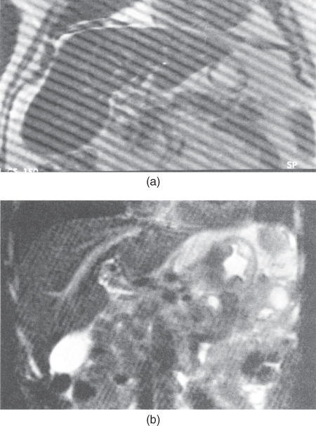
Figure 9.21 Spikes. Transient electrical discharges (spikes) during the data collection period produce a banding pattern that is superimposed across the entire imaging field. The direction and spacing of the bands depend on the timing of the discharge relative to the collection of the central phase-encoding steps.
External interference artifacts occur when there is a source of time-varying signal detected by the receiver. They appear as lines of constant frequency within the image. Their positions depend on the receiver bandwidth of the sequence and the frequency difference from the transmitter. The most common example of this is from the alternating nature (AC) of standard electrical current (60 Hz in the United States, 50 Hz in Europe and Asia) (
Figure 9.22). Electrical connections for any equipment, such as external patient monitoring devices used in the scanner room, should be filtered before being allowed to penetrate the Faraday shield or the use of nonalternating (DC) current should be considered. Manufacturers should be consulted before incorporating any electrical equipment into the scan room to ensure compatibility with the MR scanner.

Figure 9.22 External interference: (a) artifact due to electrical source outside the scan room; (b) interference from portable patient medication unit operating in scan room during the measurement (arrows).