Flash gives you a gazillion tools to modify the drawings that make up your animations. You can stack, rearrange, and reposition each individual graphic element, transform (shrink and squish) them, move them, apply color effects, and more until you're completely satisfied with the way they look. It's a cliché, but it's true: When it comes to drawing in Flash, you're pretty much limited only by your imagination. This section acquaints you with the most powerful tools Flash has for modifying the lines, shapes, bitmaps, symbols, and other graphic elements you add to your drawings.
Flash's Properties panel is a beautiful thing. Select any element on the stage, and the Properties panel responds by displaying all the characteristics, or properties, that you can change about that element.
In Figure 5-15, for example, you see several graphic elements on the stage: a brush-drawn squiggle (fill), a bitmap of a frog, a line of text, and a star. When you select the star, the Properties panel shows all the properties associated with the star: the color, width, and type of outline; the fill color; and so on. When you select the text, the Properties panel changes to reflect only text properties.

Figure 5-15. Selecting an object tells Flash to display that object's properties right there in the Properties panel. Here, the star shape is selected, so the properties all relate to the star. As long as the property isn't grayed out, you can change it in the Properties panel.
Select a shape, and you can change the properties for the fill and stroke. If it's a merge mode graphic, you can select the fill and stroke independently. If it's an object mode graphic, the fill and stroke are both selected with a single click. In either case, the properties for the selection appear in the Properties panel. For example you can change the color, the thickness, and the style of a stroke. Select the fill, and you can change the color, the opacity (alpha), or the gradient. These color options are explained on pages Advanced Color and Fills and Inserting and Deleting Keyframes and Frames.
After you have an object on the stage, you can move it around, cut it (delete it), paste it somewhere else, or make copies of it.
Tip
All the things you can do to an object—cutting, pasting, copying, and moving—you can also do to a piece of an object. Instead of selecting the entire object, just select whatever portion of the object you want to work with, and then go from there.
To move an object, simply select it (Selecting Objects on the Stage), and then drag it around the stage. Figure 5-16 shows an example of using the Selection tool to select a group of objects, and then move them together.
To cut an object, select the object (Selecting Objects on the Stage), and then choose Edit→Cut. Flash deletes the object from the stage and turns on the Paste functions.
To copy an object, select the object (Selecting Objects on the Stage), and then choose Edit→Copy. Flash leaves the object on the stage and turns on the Paste functions (see the next section).

To paste an object that you've either cut or copied, choose one of the following:
Edit→Paste in Center. This tells Flash to paste the cut (or copied) object smack in the middle of the stage's visible area, on top of any other image that happens to be there.
Edit→Paste in Place. This tells Flash to replace the cut object, or to put the copied object square on top of the original. This command is especially useful when you want to move an object from one frame to another and place it in exactly the same position in the new frame.
In the graphics world, transforming an object doesn't just mean changing the object; transforming means applying very specific shape and size changes to the object. These changes—called transforms—include some fun tricks:
Scaling. Among graphic designers, scaling means shrinking or enlarging a selected shape based on its width, height, or both.
Rotating. You can rotate (turn) an object as far as you want, in any direction.
Skewing. A limited kind of distortion, skewing means slanting an object either horizontally or vertically.
Distorting and enveloping. You distort an object by pulling it out of shape—in other words, by repositioning one or more of the object's angles. The envelope transform is similar, but it doesn't preserve the lines of the shape the way distortion does; instead, it lets you pull any angle, line, or curve out of shape to create fantastic effects.
Flipping. Flipping an object creates a mirror image of the object. Flash has commands for flipping both horizontally and vertically.
You have several choices when it comes to applying a transform to a selected object (or group of objects):
You can click the Free Transform tool (Figure 5-17), choose the appropriate option from the Options section of the Tools panel, and then, on the stage, drag your selection to apply the transform. This approach is described in the following sections.
You can open the Transform panel (Window→Transform) and then type information (for example, the number of degrees you want to rotate an object) directly into the Transform panel.
You can choose Modify→Transform, and then, from the pop-up menu that appears, turn on the checkbox next to the transformation you want to apply.
You can right-click an object and choose Transform from the shortcut menu.

To resize a drawn object, first select the object on the stage, and then proceed as follows:
Select the Free Transform tool's Scale option.
Black squares appear at the corners and sides of your selection.
Position your cursor over one of the black squares.
Your cursor turns into the double-headed scale arrow (Figure 5-18, top).
Figure 5-18. Top: Mousing over any of the black squares on the sides and at the corners of your object displays a scale arrow. By dragging a square, you can scale an object's height, width, or both. Notice that before the scaling begins, the Transform panel displays the original width/height dimensions as 100% and 100%. Bottom: Flash automatically plugs the new dimensions into the Transform panel on the bottom. Instead of dragging the object to scale it, you can also type or scrub the scale dimensions into the Transform panel yourself.
As you drag outward, the selection gets larger; as you drag inward, the selection gets smaller. You can see an example of a scaled object at the bottom of Figure 5-18.

To rotate a drawn object around its axis, first select the object on the stage, and then proceed as follows:
Select the Free Transform tool's Rotate and Skew option.
Flash displays a black bounding box around your selection.
Position your cursor over one of the black squares you see at the corners of your selection.
Your cursor turns into a circular rotation arrow (Figure 5-19, top).
Figure 5-19. Top: After you select the Rotate and Skew option, mousing over any of the black squares at the corners of your object displays a rotation arrow. Notice that before the rotation begins, the Transform panel displays the original rotation as 0.0%. Drag to rotate the object on its center axis (its transformation point). Bottom: After you let go of your mouse, Flash automatically records the rotation degrees into the Transform panel on the right. Instead of dragging the object to rotate it, you can also type the degree of rotation into the Transform panel yourself.
Drag to rotate the selection.
If you drag your cursor to the right, the entire selection rotates right; if you drag your cursor to the left, the selection rotates to the left. There's a rotated object in Figure 5-19 (bottom). Shift-drag to make an object rotate 45 degrees at a time. Alt-drag (Option-drag) to make your selection rotate around the anchor point on the opposite side from the cursor.

Tip
You can flip your objects, too, by using Modify→Transform→Flip Vertical and Modify→Transform→Flip Horizontal. The effects are a little different from rotating, as explained in Figure 5-20.

Figure 5-20. At first glance, the effects of the Flip Vertical and Flip Horizontal commands seem similar to rotating an object by 180 degrees. You notice the difference if your object contains text. For example, here you can see that Rotate 180 degrees actually spins the two blocks, whereas Flip Horizontal creates a mirror image.
To give your drawing a slanted shape, first select the object on the stage, and then proceed as follows:
Select the Free Transform tool's Rotate and Skew option.
Flash displays a black bounding box around your selection.
Position your cursor over one of the lines of bounding box, but avoid the square handles.
When the cursor is over the bounding box lines, you see the skew arrow (Figure 5-21, top). If your cursor is over one of the bounding box handles, you see the scale arrow.
Drag to skew the selection.
Dragging slants the selection along one of its axes (the one marked by the skew arrow you clicked) in the direction you're dragging. Figure 5-21 (bottom) shows a skewed object. Alt-drag (Option-drag) to make the selected object skew around the transformation point, which is usually the center.

Figure 5-21. Top: After you select the Rotate and Skew option, mousing over the bounding box lines displays a skew arrow. Notice that before the skew begins, the Transform panel shows the Skew radio button turned off. Drag to skew the object. Bottom: After you let go of your mouse, check the Transform panel: Flash automatically turns on the Skew button and logs the horizontal and vertical skew degrees. Instead of dragging the object to skew it, you can also turn on the Skew button and type the horizontal and vertical skew degrees into the Transform panel yourself.
For more freedom than simple skewing, you can distort your drawn objects in any way or direction:
First, select the object you want to distort, and then select the Free Transform tool's distort option (Figure 5-17).
Flash displays black squares around the sides and corners of your selection.
Position your cursor over one of the black squares.
Your cursor turns into a tailless distortion arrow (Figure 5-22, top).
Figure 5-22. Top: After you select the distort option, mousing over any of the black squares at the sides and corners of your object displays a distortion arrow, which you can drag to distort the object. You can drag as many distortion points as you like. Bottom: After you let go of your mouse, Flash displays the distorted object.
Drag to distort the selection.
As you drag outward, the shape bulges outward; drag inward, and the shape dents inward. Figure 5-22 (bottom) shows a distorted object.

As discussed on Pasting graphics, an envelope transform is the most radical distortion. It gives you more distortion points than the regular Distort option, and also gives you finer control over the points by letting you drag inward or outward to create rounded bulges or dents (not just pointy ones). Here's how to use the envelope distortion:
Click the Free Transform tool.
The Free Transform options appear in the Options section of the Tools panel.
Select the object you want to distort.
Flash highlights the selected object with a black bounding box and tiny black squares.
Click the envelope option.
The selected object appears surrounded by a series of black squares and circles.
Position your cursor over one of the black squares or circles (distortion points).
Your cursor turns into a tailless distortion arrow.
Drag to pull the selection into a new shape (Figure 5-23).
You'll notice that the envelope transform gives you a lot more distortion points to choose from than the distort transform; it also gives you finer control over the points you choose to distort (by dragging inward or outward).
You can see the results of modifying several distortion points in Figure 5-23.
Until Flash CS4 came along, it wasn't easy to make an object look as if it were moving in three dimensions. For example, if you wanted to make an image look like as if it were traveling away from the viewer, about all you could do was move it slightly on the stage and make it smaller. There was no real science to the effect; the best you could do was eyeball it. Creating a 3-D rotation effect was even more difficult. But no more. Flash now has tools that automatically create exactly these two effects. Next to the selection tools, there's another tool that looks like a globe with some circles drawn around it, shown in Figure 5-24. Press and hold that button, and you find the two tools that turn the stage into a 3-D world. The globe lets you rotate an object three-dimensionally, while the tool with three arrows lets you move an object around in 3-D space.

Figure 5-23. This shape began life as a square. The top and right side were transformed using the Envelope option. Mousing over any of the black squares or circles at the sides and corners of your object displays a distortion arrow. Drag to reshape your object. The squares remain attached to the outline as you drag. The circles are curve control handles.

Figure 5-24. Flash has two tools that let you move movie clip symbols in three dimensions. The tool that looks like a globe rotates movie clips. The tool with the three arrows lets you move movie clips in three dimensions.
One catch is that the object has to be a movie clip or a TLF text field. (For details on text fields, see Copying Color with the Eyedropper). This isn't too much of a catch, because you can put any object inside a movie clip—like your logo or some text—and then make it fly and spin in 3-D. The other catch is a bit more limiting, since Flash's drawing tools create only two-dimensional images. For example, you can create squares but not cubes, and circles but not spheres. The text tool creates only two-dimensional type, not 3-D letters. But once these objects are placed inside movie clips, you can move those movie clips around in three dimensions. It's sort of like moving a photo of a car around in 3-D space as opposed to moving a model car around the same space. But even with those limitations, you can create some pretty snazzy effects.
Note
Because the 3-D tools are a relative newcomer to Flash, they won't work if you choose the ActionScript 2.0 option (see Starting Flash) and they rely on Flash Player 10 or greater—an option you choose when you publish your animation (8. Group elements).
The 3-D pros refer to rotating an object as transforming an object or a transformation. Here are the steps for rotating a movie clip in 3-D:
Select the object or group of objects you want to spin, and then press F8 to convert them into a movie clip symbol.
You can combine objects in a movie clip. For example, Figure 5-25 shows a circle and text combined in one movie clip.
On the stage, select the movie clip, and then click the 3-D Rotation tool in the Tools palette.
A globe-like image appears near the movie clip, made up of colored circles. Each color represents a 3-D axis. The small circle in the center marks the point around which the rotation happens.
Drag the center point to change the point around which the rotation takes place.
You can drag the center point to any location on the stage or even off the stage.
Click one of the colored lines in the 3-D rotation tool to rotate the movie clip along that axis.
As you hold the cursor over one of the colored axes, a tooltip appears indicating the axis around which the object will rotate. For example, move the cursor near the green line and a Y appears on the cursor, meaning that the selected object will rotate around the Y axis. You can think of the Y axis as a line that runs from the top of the stage to the bottom. The red line in the sphere represents the X axis, and the blue circle represents the Z axis, which you can think of as a line running from the viewer back into the stage. The easiest way to get your bearings is to experiment. Try the different options and click Undo (Ctrl+Z or ⌘-Z) if you don't like the results. If you don't want to be limited to spinning along a standard XYZ axis, then drag the orange ring around the outside of the other circles. That way, the object is free to follow your mouse movement in any direction.

The 3-D pros refer to moving an object in three dimensions as translating an object or a translation. Here are the steps for moving a movie clip in 3-D:
On the stage, select the movie clip you want to move in 3-D.
Make sure the object you want to move is a movie clip symbol. If not, press F8 to make it into one.
In the Tools palette, click and hold the button for 3-D rotation tools, and then choose the 3D Translation tool from the menu.
In the tools panel, the 3D Translation Tool looks like three arrows pointing in different directions. After you click the button, a 3-D translation icon appears over the selected movie clip on the stage. The 3D Translation icon looks like a red and green arrow protruding from a large dot. As shown in Figure 5-26, each arrow is a different color to represent an axis along which the movie clip can be moved. Green moves the object vertically (the Y axis). Red moves it horizontally (the X axis). The big represents the Z axis.
Drag one of the colored arrowheads or the dot to move the movie clip along that axis.
When you hold the cursor over one of the arrowheads or the dot, a tooltip appears indicating the direction of the axis: X, Y, or Z. In addition to using the 3D Translation tool, you can also use the Properties panel to move objects along the three axes (Figure 5-27). Select the movie clip you want to position, and then use the 3D Position and View X, Y, and Z settings to move it around the stage. Click a setting and type a number, or drag to scrub in a number.

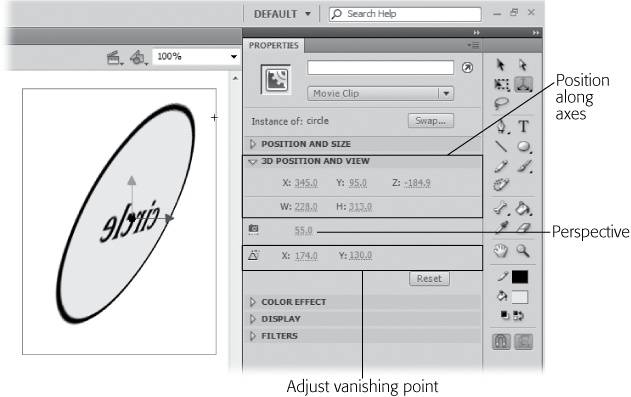
You can set two 3-D properties in the Properties panel: Perspective and Vanishing Point (Figure 5-28). Choosing a perspective setting is similar to choosing a lens for your camera. Flash starts you off at 55, a "normal" point of view similar to a 55mm lens on a camera. Set the number higher, and it's like you're zooming in or attaching a telephoto lens. Choose a lower setting, and it's as if you attached a wide-angle lens. You can add some creative distortion to your images using the Perspective setting, along with some of the other 3-D tools.

Figure 5-28. The icon for setting the perspective looks like a camera because it's similar to changing camera lenses between normal, telephoto, and wide angle. Use the X/Y Vanishing Point settings to position the vanishing point in your animation.
Think back to your art class days when you learned how to add a vanishing point to your drawings to help you draw in perspective. The vanishing point is that place way off in the distance where all parallel lines seem to converge. In Flash, you can move the vanishing point around in your animation using the X/Y settings in the Properties panel (Figure 5-28).
Note
You can add these same 3-D effects to your motion tweens when you use the Motion Editor. For the details, see A Tour of the Motion Editor.
In Chapter 4, you learned how to stack objects to create composite drawings using layers. But you don't need layers to place one item on top of another. You can overlap two or more objects on the same layer, but there are a few issues to consider:
You can't stack ungrouped shapes, which includes any lines and fills you've created in merge mode, because the cookie cutter effect takes place. See the box on Safety in Groups for details.
Objects drawn in merge mode always appear below objects drawn in object mode.
If you try to tween two objects that aren't grouped or enclosed in a single symbol, you get unexpected results.
The instant you create two or more overlapping object drawings on the stage, though, you need to think about stacking, or arranging them. Stacking tells Flash which object you want to appear in front of the other.
In Figure 5-29, for example, you see three object drawings: a rectangle, a circle, and a star. They were drawn in object mode in that order, so Flash stacks them one on top of the other with the rectangle first, then the circle on top of the rectangle, and the star at the top of the stack. Flash keeps track of the stacking order even if the shapes aren't overlapping one another. So, when you drag the rectangle and drop it on top of the star, Flash displays the rectangle behind the star. Then, when you drag the circle and drop it on top of both the rectangle and the star, Flash displays the circle behind the star, but in front of the rectangle, as shown in Figure 5-31. If that's the effect you want, great; if not, you can change the stacking order of all three shapes.
To stack objects on the stage:
Select the object you want to rearrange (either to push behind or pull in front of another object).
In Figure 5-30, the circle's selected.
Figure 5-29. Stacking isn't an issue when your objects don't touch one another. The instant you drag one object on top of another, though, you have to decide which object you want to appear on top, and which behind.
Figure 5-30. When you create shapes in object mode, Flash puts the first shape on the bottom of the stack and each new shape is placed on top of the stack. Ungrouped (merge mode) objects are an exception to the rule. Ungrouped objects are always placed behind object drawings. See the box on page 181 for more details.
Choose Modify→Arrange, and then, from the submenu, change the object's stacking order.
Here are your options:
Bring to Front. Pulls the selected object all the way forward until it's on top of all the other objects.
Bring Forward. Pulls the selected object forward one position, in front of just one other object.
Send Backward. Pushes the object back one position, behind just one other object.
Send to Back. Pushes the selected object all the way back, until it's behind all the other stacked objects.


Tip
To quickly move a selected object forward and backward, use Ctrl+up arrow or Ctrl+down arrow (⌘-up arrow and ⌘-down arrow). Ctrl+Shift+up arrow (Shift-Option-up arrow) brings the selected object all the way to the front and Ctrl+Shift+down arrow (Shift-Option-Down) sends it all the way to the back.
Figure 5-31 shows you an example of choosing Bring Forward with the circle selected. There is a way to make shapes drawn in merge mode behave like object drawings when you stack them. The trick is to group them. Select the fill, stroke, and anything else you want to include in a group. Then choose Modify→Group (Ctrl+G or ⌘-G). The selected objects are now part of a group that you can position using commands like Bring Forward or Send to Back. For details, see the box on Safety in Groups.

Figure 5-31. To restack an object, you need to select it first. Here, you see the circle selected. Choosing Bring Forward will bring the circle forward one position, placing it on top of the star. The "Bring to Front" and "Send to Back" commands give you a quick way to move objects to the top or bottom of the stack.
As you saw in Chapter 2 (Choosing a Drawing Mode), Flash treats lines and fills differently when you're working in merge drawing mode. For example, take a look at Figure 5-32, which shows a line drawn with the Pencil and a line drawn with the Brush.

Figure 5-32. Top: When you're working with ungrouped objects (which is what you create in merge drawing mode), the Selection tool behaves differently. Here, you see the results of clicking the Pencil-drawn line: Flash selects only a portion of the line (a single stroke). Bottom: Clicking the Brush-drawn line, on the other hand, selects the entire line. This behavior is just one example of how Flash treats strokes and fills differently.
If you click the Selection tool and then click to select the Pencil-drawn line, Flash highlights just one segment of the line. But performing the very same operation on the similar-looking Brush-drawn line selects the entire line.
When you convert a line into a fill, Flash lets you interact with the line just as you would with any other fill. This technique is especially useful when you're working with shapes, no matter which drawing mode you're using. That's because when you create a shape using one of Flash's shape tools—a star, say, or a circle—Flash actually creates two separate elements: the inside of the shape (a fill), and the outline of the shape (a stroke). If you want to change the color of the entire shape, you need to use two tools: the Paint Bucket tool (which lets you change the color of fills), and the Ink Bottle tool (which lets you change the color of strokes, or add a stroke to an existing fill). When you convert the outline to a fill, Flash lets you manipulate both the outside and the inside of the shape in the same way using the same tools. Converting also lets you create scalable shapes (images that shrink evenly) and nice, straight corners (thick strokes appear rounded at the corners; thick fills shaped like lines don't).
To convert a line into a fill:
Select the line (or outline) you want to convert into a fill.
Flash highlights the selected line.
Choose Modify→Shape→Convert Lines to Fills.
Flash redisplays the line as a fill, and the Properties panel changes to display fill-related properties (as opposed to line-related properties).
In Chapter 2 (Adding Measurement Guides), you saw how to use Flash's grid, guides, and rulers to help you eyeball the position of objects as you drag them around on the stage. You also saw how to use the Alignment panel to line up objects with respect to one another or to one of the edges of the stage.
Both these approaches are useful—but Flash doesn't stop there. Snapping and guide layers give you even more control over where you place your objects with respect to one another on the stage.
Snapping is one of those features people seem to love or hate. The key to snapping is to turn it on when you need consistent alignment and to turn it off when it cramps your style. Here's how it works: When you turn snapping on, you tell Flash to help you out when you're positioning objects on the stage. Snapping helps in a few ways. For one, it provides guidelines when elements are aligned. And it also makes items snap into place when they're close. You don't have to be a mouse marksman.

Figure 5-33. Top: When you turn on snapping, Flash gives you a visual cue when you drag an object close to alignment. Here, Snap Align is turned on, so Flash displays a dashed line when the edges of the circle are aligned with the edges of the stroke. You tell Flash how close is close enough using the Horizontal and Vertical Object Spacing fields of the Edit Snapping window, which you display by choosing View→Snapping→ Edit Snapping, and then, in the Edit Snapping window that appears, clicking Advanced. Bottom: In this example, Snap to Objects is turned on, too. The point where the oval is clicked shows a circle; when that point is close to the stroke, the circle gets larger and bolder. Let go of the mouse button and the oval snaps into place.
For example, in Figure 5-33, you see an oval being dragged across the stage. Because Snap Align is turned on, Flash displays a dashed line (top) when the circle is dragged so that one or more of its edges is aligned with another object in your animation. Snapping also creates a snapping point at the point clicked or, if you click close to the center of an object, in its center.
Tip
For snapping to work, you can't speed around the stage; if you do, you'll miss Flash's cues. Instead, drag your objects slowly.
To turn on snapping, select View→Snapping, and then, from the shortcut menu that appears, choose one of the following:
Snap Align. Displays a dashed line when you drag an object within a certain number of pixels (you see how to change this number in the box on this page) of another object or of any edge of the stage.
Snap to Grid. Displays a small, thick circle where you select an object. This point snaps to points in the grid. See Adding Measurement Guides for details about displaying a grid. If you click near the center, Snap assumes you meant to select the center of the object, so that's where it places puts the circle snapping point.
Snap to Guides. Works similarly to Snap to Grid except that the snapping action works with guides that you drag out from the rulers and place individually. For more on guides, see Adding Measurement Guides.
Snap to Pixels. Useful only if you want to work at the single-pixel level (your stage has to be magnified to at least 400% for this option to work). This option prevents you from moving an object in any increment less than a whole pixel. (To magnify your stage by 400%, select View→Magnification→400%; when you do this with Snap to Pixels selected, a single-pixel grid appears.)
Snap to Objects. Displays a small, thick circle on your object when you select it. As you drag that object close to another object on the stage, Flash uses that point for snapping. The actual location of the snapping circle depends on where you click the object you're moving. Flash does its best to guess whether you want to select the center, the edge, or some other point.

If you've ever traced a drawing onto a piece of onionskin paper, you understand the usefulness of guide layers in Flash.
A guide layer is a special kind of layer that doesn't appear in your finished animation, but that you can hold beneath your stage while you're drawing to help you position and trace objects. Say, for example, you want to align objects in a perfect circle, or on a perfect diagonal, or you want to arrange them so that they match a specific background (say, an ocean scene). You create a guide layer and, on it, draw your circle or diagonal or ocean scene. Then, when you create your layer, your guide layer shows through so you can position your objects the way you want them. When you go to run your animation, though, you don't see your guide layer at all; it appears only when you're editing in Flash.
To create a guide layer:
On the stage, draw your guide shapes or lines, or add a tracing image, as shown in Figure 5-35.
This first layer contains the "guide" material. Later, you add one or more layers with the images you want to appear in your animation.
Position your cursor over the name of the layer you want to turn into a guide layer, and then right-click.
Flash displays a pop-up menu.
From the pop-up menu, select Guide.
Flash displays a little T-square just before the layer name, as in Figure 5-35.
With the guide layer still selected, create a new, regular layer for your objects by choosing Insert→Timeline→Layer.
Flash creates a new layer and places it above the guide layer, as shown in Figure 5-35.
Tip
Working with layers—especially guide layers—can be confusing if you're not used to it (and, frankly, it can be confusing even if you are used to it, especially if you're working with a lot of layers). To make sure you don't inadvertently modify your guide layer, you can lock it (tell Flash not to let you edit it temporarily). To lock your guide layer, click the dot beneath the padlock icon. The dot changes to a padlock. Then, when you click to select your regular layer, you can align away without worrying about accidentally changing your (locked) guide layer.
Select View→Snapping, and then, in the context menu that appears, turn on the checkbox next to Snap to Objects. You've turned snapping on.
Turning snapping on helps you position your objects on your guide layer. Both Snap to Objects and Snap Align are helpful when you work with a guide layer.
With the regular layer selected, draw, trace, or move your objects.
You can then drag objects to your guideline (or guide object, or guide background) or use objects in the guide layer for tracing. When tracing a cutout, as in Figure 5-35, temporarily adjust the alpha (transparency) setting of objects you want to see through.

Figure 5-35. Here the guide layer is used in two different ways: for alignment and as a tracing tool. The arrow and the cameo profile are both on the guide layer. On the left, the oval is being dragged, and it snaps to the edge of the arrow. On the right, the cameo was used to trace the shape of the head with the freehand Lasso.